HOW DOES IT WORK?
This page continues the story about RIMS / HERMS and is divided in the following paragraphs:
- Introduction: an introduction of the brewing setup, with a few pictures
- Glossary: explanation of a few common used terms
- The start of the brewing process: a description how the brewing setup is powered up
- Mashing phase: a description how mashing is done
- Sparging phase: a description how sparging is done
- Boiling phase: a description how boiling is done
- Chilling phase: a description how cooling of the wort is achieved
- And? How does it work? a description of some results, with a few graphs
Every individual phase, along with the coordination of these phases, is being taken care of by the brew program. So any description of an event here is fully automated by this brewing program. Screenshots of the brewing program are given as well.
INTRODUCTION
The current brewing setup is fairly complex. It is something different than the two small pans that I used in the early days. The brewing setup consists of a number of major components (if you wish to read more details about every component, have a look at the brewing setup):
- The PC: this is a NUC running windows 10, which runs the custom made software program e-brew
- The electronics: All the electronics, necessary for controlling the brewing system, are located here
- The pans / brew kettles: these pans have sizes of 200 L (Hot Liquid Tun, HLT), 110 L (Mash/Lauter Tun, MLT) and 140 L (boil kettle).
- The magnetic pump: the heart of the brewing setup, this pump takes care of transferring fluids from any kettle to another
- The counter flow chiller (CFC): this is the cooler, that cools down the hot wort from the boil kettle down to room temperature
- The gas burners: two burners of 24 kW each (!), adjustable from 0 % to 100 % power (modulating)
- The temperature sensors: represented with TI in the schematic. There are two temperaturesensors for the HLT, two for the MLT, one for the boil-kettle and one at the output of the CFC
- The flow sensors: represented with FI in the schematic. These sensors measure the amount of litres flowing through it
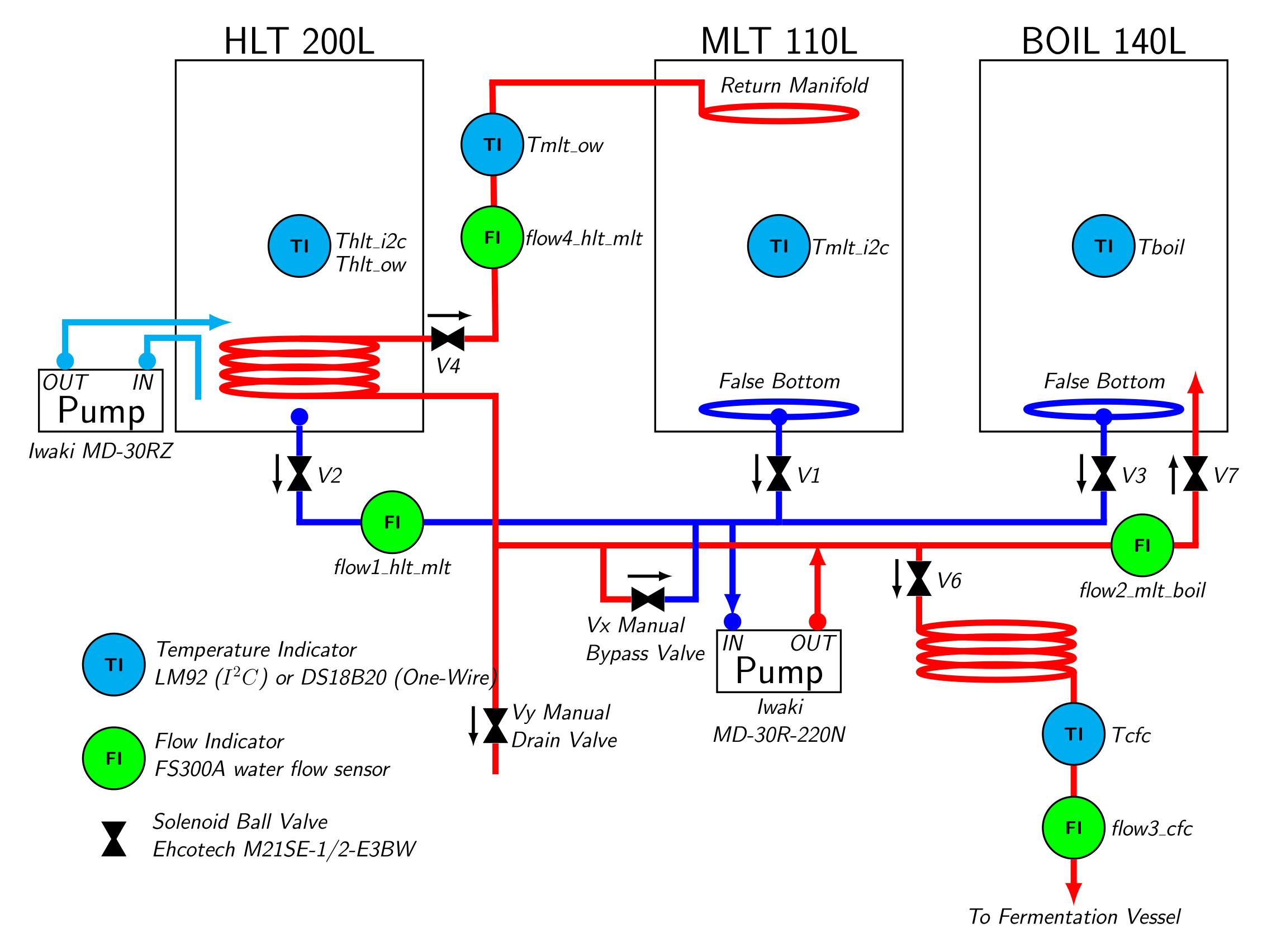
This brewing setup is a so-called HERMS system.
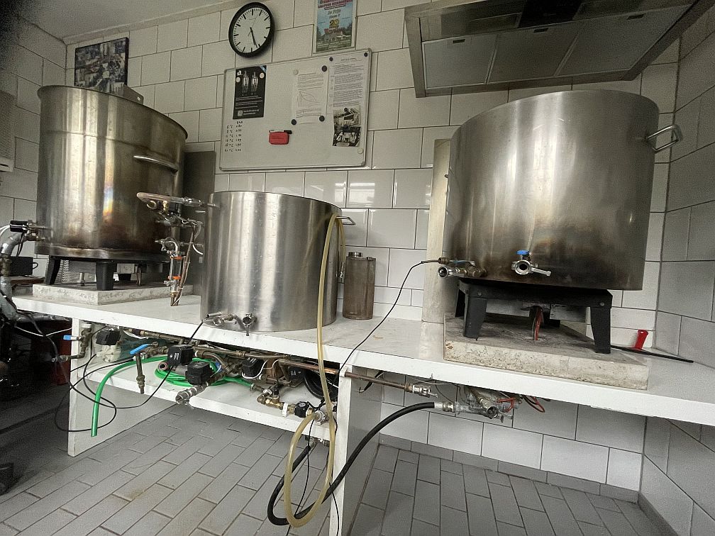
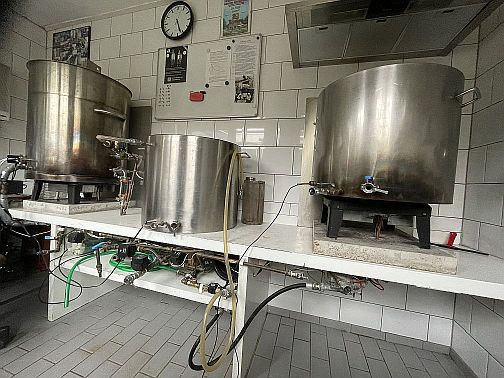
The picture shows most of the brewing setup. The Hot Liquid Tun (HLT) is shown on the left side, The Mash/Lauter Tun (MLT) is shown in the middle and the boil kettle is shown on the right. The pump and the CFC are not really visible (behind the copper pipes and the green hose in the lower compartment).
GLOSSARY
There are some specific words, used in the illustration. These words are:
- HLT, Hot Liquid Tun: this is the kettle that contains all the warm water needed for mashing and sparging. This pan can contain up to 150 L of water
- MLT, Mash Lauter Tun: this is the kettle, where mashing takes place. It contains the malt with the water. This is a double-walled pan, with isolation in between. The total net volume is 110 L.
- Boil, the boiling kettle. The result (called the 'wort') from the mashing phase is collected here. The hops are added to the wort, and then the wort is brought to a boil for 2 hours.
- CFC, Counter Flow Chiller. The beer from the boil kettle is cooled down to room temperature by this component. The cooled down wort is then pumped to the fermentation bin.
- V1 .. V8: these are solenoid ball valves. Such a valve opens when an electric voltage is applied to it.
- Fermentor: the fermentation bin. This is a Brewtools F100 Unitank and/or four Grainfather Conical Fermenters of 25 L each.
THE START OF THE BREWING PROCESS
I start by rinsing all the pipes. Then I close all valves, except for Vx. This valve has a special function, that of pump by-pass. You can use it to regulate the net flow through your system (I have measured values between 3 and 12 litres per minute). Next I check all the pipes (connected with quick-connect couplings) to see if they do not leak.
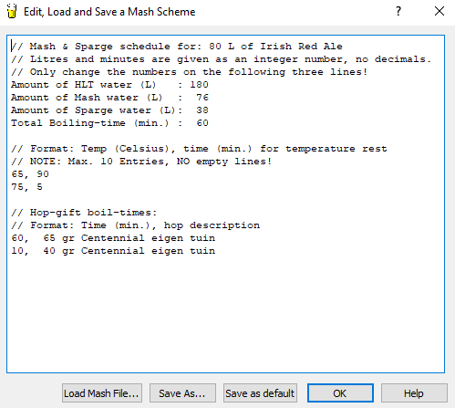
Next, I fill the HLT with fresh water, then the brewing program takes over. First thing to do is to load the mash-scheme file. This is a text-file which can be edited with any text-editor, but you can also use the internal editor. After pressing 'Save as default', the values will be using in the brewing program.

After the button 'HLT PID Controller' is pressed (the LED then turns green), the program starts with heating the water inside the HLT, until the first temperature from the mash-scheme is reached (65 °C in this case) plus a parameter value (via Options -> Brew Day Settings... -> Mashing).
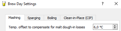
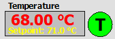
If this value is set to 6.0 °C, the reference temperature for the HLT will become 71.0 °C. This setpoint value is displayed in the HLT temperature block.
The label that displays the current state of the program ('Current STD State'), will display the following:
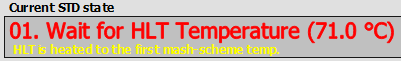
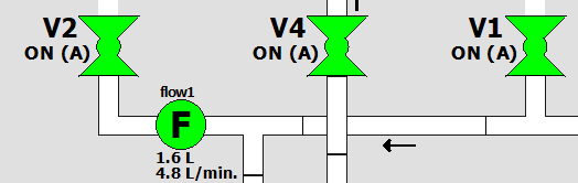
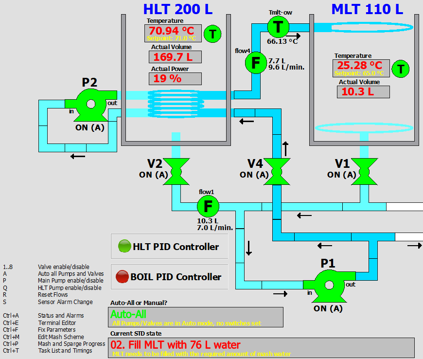
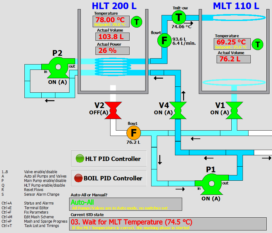
After the HLT temperature has reached the setpoint value, the next state will be 'Pump Prefill'. In this state, the valves V1, V2 and V4 are opened, so that water from the HLT is flowing through the pump and into the MLT. Flowmeter flow1 turns green to indicate that it sees a flow through it.
After one minute, the next state is entered. This is 'Fill MLT with 76 L water'. The 76 L comes from the mash-scheme file. The program switches on the pump, so that the required amount of water is pumped from the HLT into the MLT. During this, valve V1 is opened, so that there is already a flow from the MLT through the pump, through V4, through the heat-exchanger (in the HLT) and back again to the MLT. This reduces the volume in the HLT, but increases the MLT volume at the same time. After reaching the desired volume in the MLT, valve V2 is closed (the pump remains on all the time), so that no water from the HLT comes in anymore. The water now circulates continuously from the MLT, through V1, through the Pump P1, to the heat-exchanger in the HLT and back to the top of the MLT.
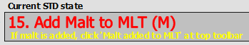
The program now waits until the correct MLT temperature is reached. The next state will then be '19. Ready to add Malt to the MLT (M)'. I usually wait a bit more until the MLT temperature is a few degrees higher. This make sure that when you add the grains to the water, the correct strike-temperature is obtained. If that temperature is obtained, an 'M' needs to be pressed on the keyboard to enter state 15 'Add Malt to MLT (M)'. All valves and the pump are now switched off, so that the milled grains can be added to the water inside the MLT.
After adding the grains and stirring well, a 'M' can be pressed again. This activates state 18 ('Mash Rest'). This mash-rest is only active when the option 'Enable Mash Rest (5 minutes) is checked in the Menu Options -> Brew Day Settings... -> Mashing. Best thing to do is to set this to checked, so that the filterbed can not get stuck. There's a risk of clogging if the pump is switched on directly after adding the grains.

THE MASHING PHASE
After the mash-rest of 5 minutes, the mash-fase itself is activated ('04. Mash-Timer Running'). The mash water is being circulated continuously (MLT -> V1 -> pump -> V4 -> HLT heat exchanger -> MLT). This is seen in the screenshot by following the colored pipes. This mash-temperature (65 °C) is being held for 90 minutes and during this time the wort is pumped this way.
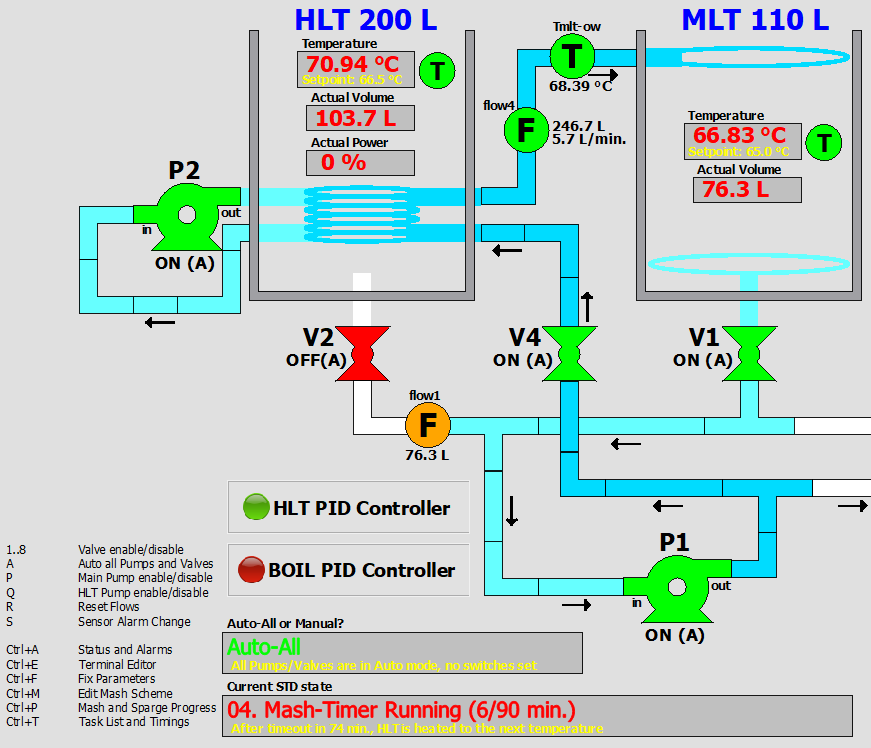
The program also calculates when the HLT burner should be enabled again to reach the next mash-temperature. The mash-scheme file used here has a second temperature of 75 °C, the program calculated that it needs 16 minutes of heating before this temperature is reached. So if the program enables the HLT burner 16 minutes prior to ending the current mash-timer, the HLT is heated in time for the next mash-temperature. This is seen in the following screenshot:
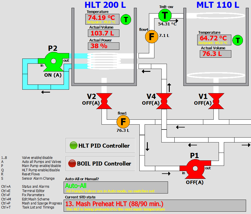
In this state ('13 Mash Preheat HLT'), the valves and the pump are all off, the HLT is heated to the next temperature and the MLT temperature stays quite close (now at 64.72 °C) to the current mash-temperature.
After this temperature is reached, the next mash-phase is entered, which is the same state as before ('04. Mash-Timer Running'). If the mash-scheme file contains five temperature-time pairs for mashing, this cycle also runs five times. After the time-out of the last temperature (in this case 75 °C), mashing is complete and sparging phase is entered.
THE SPARGING PHASE
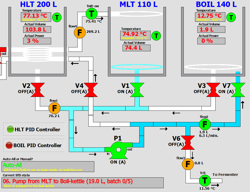
After mashing is complete, a part of the wort is pumped to the boil kettle. This happens in state 6 'Pump from MLT to Boil-kettle', see screenshot below. The wort goes through V1 to pump P1, then to flowmeter 2 and V7 into the boil-kettle. Flowmeter 2 has to see a flow-rate and this is also the case. Eventually flowmeter 2 will show the volume of all wort entered into the boil-kettle.
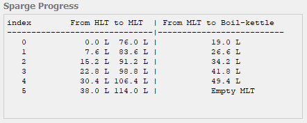
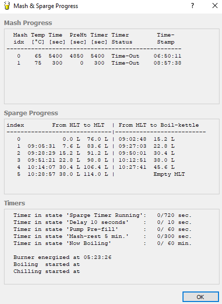
Progress of sparging can be made visible with the 'Mash & Sparge Progress' screen (View -> Mash & Sparge Progress or by pressing Ctrl-P). The screen shows that there are five sparging phases, that on the first time 19 L is pumped to the boil-kettle, and 7.6 L on the other phases. Every sparging phase also pumps 7.6 L fresh water from the HLT to the MLT. The mash-scheme file shows that the total amount of sparging water equals 38 L, with five sparging phases, this is 7.6 L per phase.
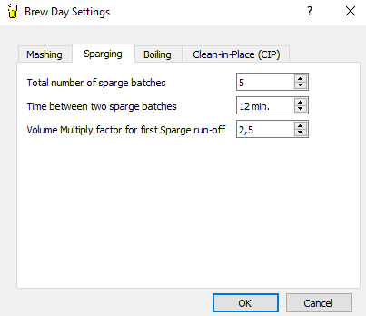
Besides the information from the mash-scheme file, you also need the information from some sparging parameters. These can be found via Options -> Brew Day Settings... -> Sparging. The last parameter ('Volume Multiply factor for first Sparge run-off') determines the amount of liters for the initial run-off to the boil-kettle. In this case we already calculated that each sparging phase had 7.6 L to pump to the boil-kettle, the number of liters for initial run-off then equals 7.6 * 2.5 = 19.0 L.
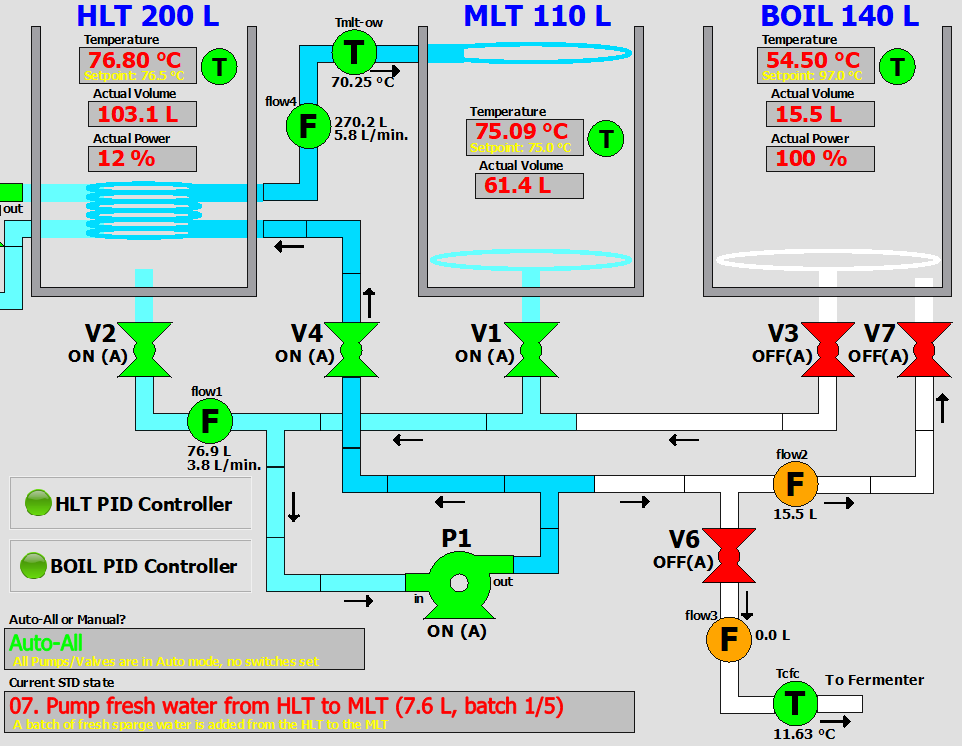
After wort is pumped from the MLT to the boil-kettle, new fresh water from the HLT is pumped to the MLT. The HLT waterlevel will decrease, while the MLT waterlevel will increase with the same amount. This happens in state 07 ('07. Pump fresh water from HLT to MLT').
After the right amount of water (7.6 L) is pumped to the MLT, the sparging phase itself is reached (state 05 'Sparge-Timer Running'). This state has continous pumping from the MLT to V1, to the Pump, to V4 and from the HLT heat-exchanger back into the MLT. The wort in the MLT is kept to the desired temperature, because it is pumped through the HLT heat-exchanger. After a time-out of the current sparging phase, there's another round of pumping wort from the MLT to the boil-kettle. This cycle is repeated for the number of sparging batches. The progress screen clearly shows the amount of sparging phases, together with the actual times when sparging took place.
BOILING
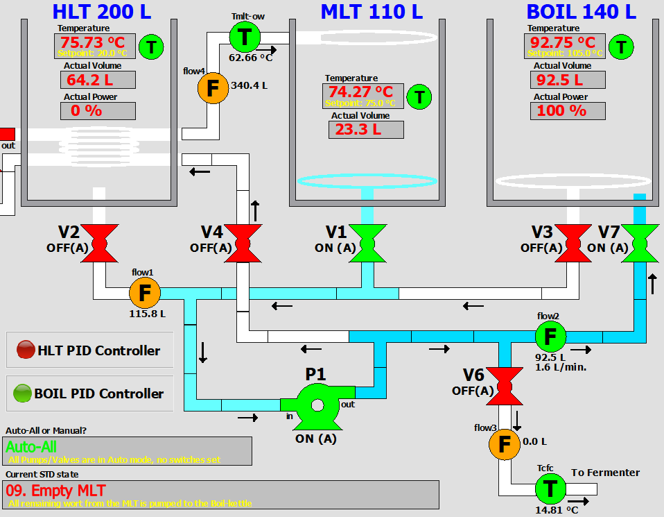
After the last sparging phase, all remaining wort in the MLT is pumped to the boil-kettle. This happens in state 9 'Empty MLT'. Here, the burner for the boil-kettle is set to 100 %, so that everything is brought to a boil as quickly as possible.
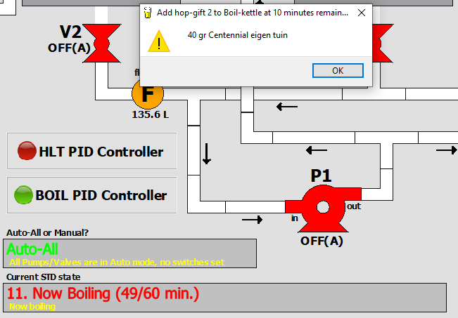
After all wort is collected into the boil-kettle, the pump is switched off. The program automatically detects when there's no flow anymore (the MLT is empty then) and will go to the next state ('Waiting for Boil (M)'. When the actual boiling-temperature is reached, a boil-timer is started. If there are any hop-gifts defined in the mash-scheme file, the program initiates a series of beeps and shows a pop-up. This happens for every hopgift during boil.
Since the wort typically needs to boil for at-least 60 minutes, this is a good moment to remove the spent grains from the MLT and to clean the MLT. It is also useful to clean the pipes of the brew-system. If there's still sufficient warm water in the HLT, you can use this to clean the pipes of the brewsystem. The pumps and valves can be used in manual mode to clean every single pipe. Afterwards, an 'A' (Auto all Pumps and Valves) can be pressed on the keyboard to get back to automatic mode.
CHILLING
When boiling is finished I let the wort rest for 5 minutes. This is enabled by checking option 'Apply time-rest of 5 minutes after Boiling' in Options -> Brew Day Settings... -> Boiling. This prevents a clogged filter in the boil-kettle, so enable this option by default. After these five minutes, the next state ('12. Boil Finished, prepare Chiller (M)') is reached. After pressing an 'M', there are two possibilities, depending on parameter 'Start Chilling with recirculating through Boil-kettle':
- Parameter is unchecked. In this case, state 16 ('Chill & Pump to Fermentation Bin (M)') is entered immediately. The contents of the boil-kettle is pumped through the counterflow-chiller directly into the fermentation-bin.
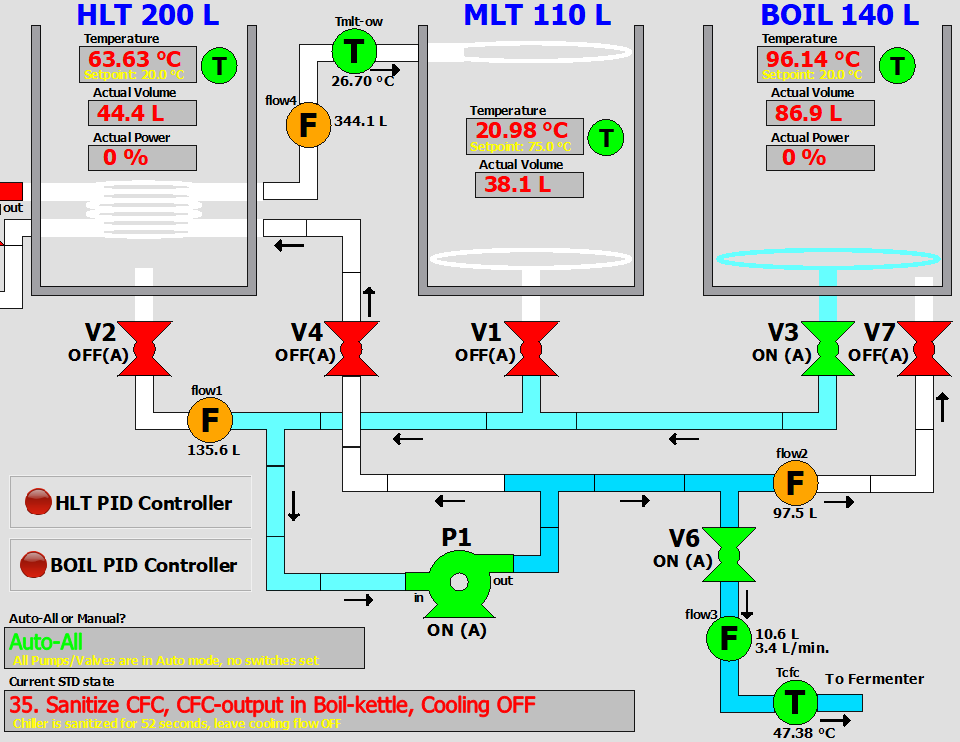
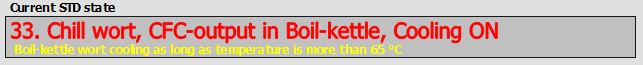
- Parameter is checked. In this case, two states are activated: state 35 'Sanitize CFC, CFC-output in Boil-kettle, Cooling OFF' and state 33 'Chill wort, CFC-output in Boil-kettle, Cooling ON'. This option is convenient in summer when the counterflow-chiller has insufficient capacity to cool directly into the fermentation-bin.
In state 35, wort is pumped from the boil-kettle through V6 and the counterflow-chiller. The tapwater supply for the counterflow chiller is switched off ('Cooling OFF') and the hose of the counterflow chiller is placed in the boil-kettle. This is done to sanitise the counterflow-chiller prior to use.
After the time-out of five minutes, the tapwater supply for the counterflow chiller is switched on and the wort in the boil-kettle is effectively cooled. This is cooled down to the temperature, as specified with the parameter 'Lower-Limit Temperature for Boil-kettle recirculation' (Options -> Brew Day Settings... -> Boiling). This parameter should not be set too low, because the wort is contagious for infections below 65 °C. The temperature in the boil-kettle is now dropping, which is an indication that the counterflow chiller does its job. The cooling water, which is now hot, can be collected to use for cleaning later on.
When this lower-limit temperature is reached, state 34 is activated and the pump is switched off. The hose of the counterflow chiller should be removed from the boil-kettle and placed inside the fermentation-bin. After pressing 'M' on the keyboard, state 16 'Chill & Pump to Fermentation Bin' is activated.
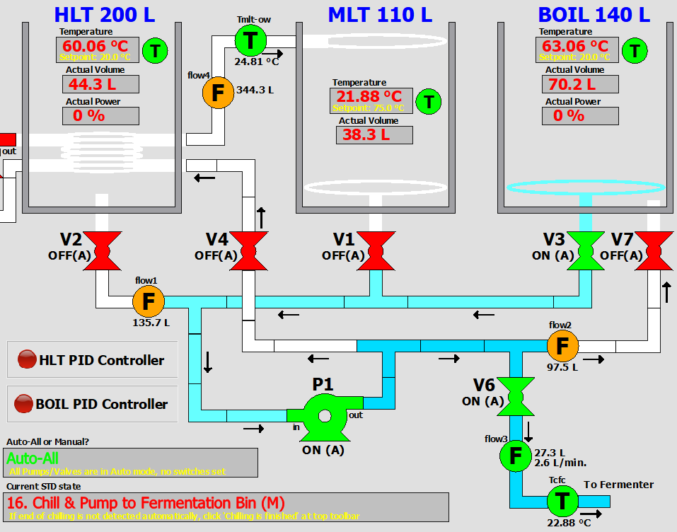 In state 16 ('Chill & Pump to Fermentation Bin') the wort from the boil-kettle is pumped through the counterflow-chiller and then into the fermentation-bin. The temperature of the wort at the exit of the counterflow-chiller can be seen with temperature sensor Tcfc (which is 22.88 °C in this case). Also the amount of liters flowing into the fermentation-bin are measured (in this case 27.3 L).
If the temperature of the wort is still too high, the pump output can be reduced a bit more, or the cooling-water supply can be increased. When all wort has been transferred from the boil-kettle (again, this is automatically detected), the brewing-day is finished and cleaning of the brewing system (pipes, kettles) can begin.
In state 16 ('Chill & Pump to Fermentation Bin') the wort from the boil-kettle is pumped through the counterflow-chiller and then into the fermentation-bin. The temperature of the wort at the exit of the counterflow-chiller can be seen with temperature sensor Tcfc (which is 22.88 °C in this case). Also the amount of liters flowing into the fermentation-bin are measured (in this case 27.3 L).
If the temperature of the wort is still too high, the pump output can be reduced a bit more, or the cooling-water supply can be increased. When all wort has been transferred from the boil-kettle (again, this is automatically detected), the brewing-day is finished and cleaning of the brewing system (pipes, kettles) can begin.
AND? HOW DOES IT WORK?
Great! I initially encountered some problems, such as a leaky pump and unreliable thermometers. But having a pump makes a big difference. Temperature is much better to control. And you don't have to walk around with heavy pans anymore. No more waiting for an hour to cool things down. I managed to save several hours compared to the setup without pump and counter flow chiller. Another advantage is the flexibility of the computer program. I wrote the program in such a way that all process parameters are adjustable, such as the number of sparging batches, or the P, I and D values of the PID controller. Parameter values are saved automatically in the Windows Registry, so that when you restart the program, these parameters are set to the latest value. And if I require functionality that can not be realised with changing parameters, I write an update of the brew program. In this way, a number of updates have been realised!
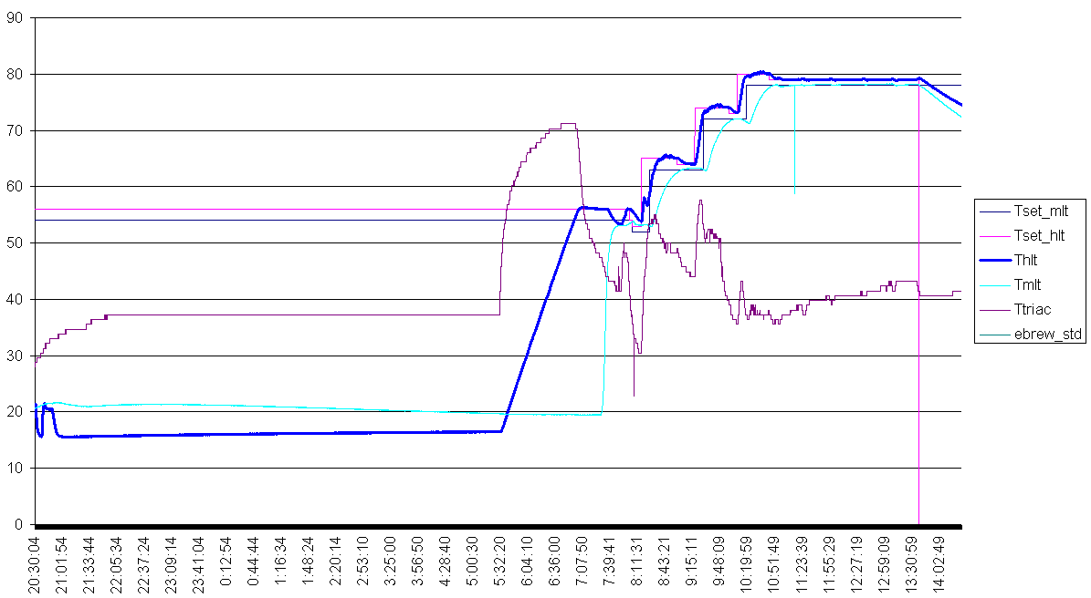
This is a graph that is reconstructed from a log-file. It shows the various temperatures during a brewing session. The brewing program writes, every 5 seconds, all relevant data into a log-file. Explanation of the graph:
- Tset_MLT: this is the reference temperature for the Mash/Lauter Tun (MLT). This should be the actual mash scheme that you want to use
- Tset_HLT: calculated by the program. It typically is set a few degrees higher than Tset_MLT in order to compensate for temperature losses
- Thlt: the measured and filtered actual temperature of the HLT, which is read from a digital (12 bit + sign) temperature sensor that is mounted inside the HLT
- Tmlt: the measured and filtered actual temperature of the MLT, which is read from a digital (12 bit + sign) temperature sensor that is mounted inside the MLT
- Ttriac: the measured actual temperature of the power electronics inside the electronics box (the system is shut down when this becomes too high)
One of the striking things in this graph are the sine-waves / ripples in the HLT temperature (yellow line). It is an indication that the PID controller has not
been set properly! The second graph (below) shows another response, but then from a properly set PID controller. The HLT temperature is, in this case,
the fat blue line.
The ripples in the previous graph are almost completely gone. The temperature is controlled to within 0.05 °Celsius. You can barely see 5 little peaks
in the graph (at the right end of the graph). These are the moments that sparging water from the HLT is transferred to the MLT. But the PID controller reacts
very well to this disturbance.
More recently I wrote a Python script to decode the logfile, created by the brewing program. I run the script in Thonny, which gives the following output:
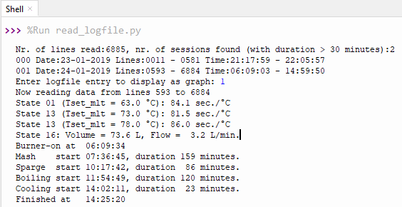
The logfile can contain multiple sessions. I chose here session 001, because that was the actual brewday session: from 06:09 to 14:59. The python script also displays a number of interesting facts, such as the average time to raise the temperature by 1 °C: 84.1, 81.5 and 86.0 seconds per °C. In state 16 "Chill and Pump to Fermentation Bin" the wort is cooled and pumped into the fermentation bin with an average flowrate of 3.2 liters per minute. Furthermore, the actual starting time and duration of the main brewing phases are given. Next, graphs are shown of emperatures, volumes and states.
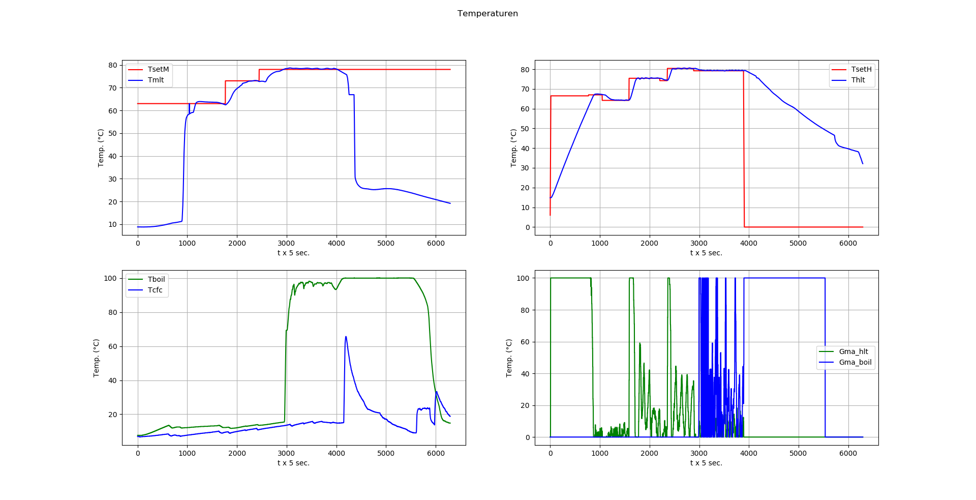
Legend: TsetM = Reference temperature for the MLT, Tmlt = actual temperature inside the MLT. TsetH = Reference temperature for the HLT, Thlt = actual temperature inside the HLT. Tboil = Actual temperature inside the boil-kettle, Tcfc = actual temperature at the output of the counterflowchiller. Gma_hlt = PID-controller output for the HLT, Gma_boil = PID-controller output for the boil-kettle
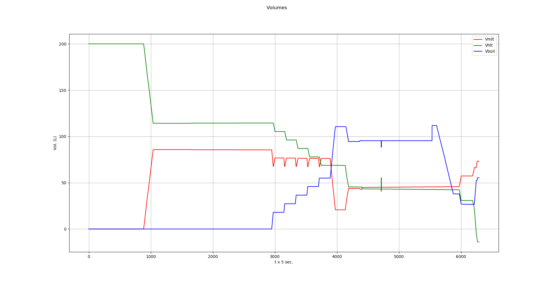
Legend: Vmlt = actual volume inside the MLT, Vhlt = actual volume inside the HLT, Vboil = actual volume inside the boil-kettle.
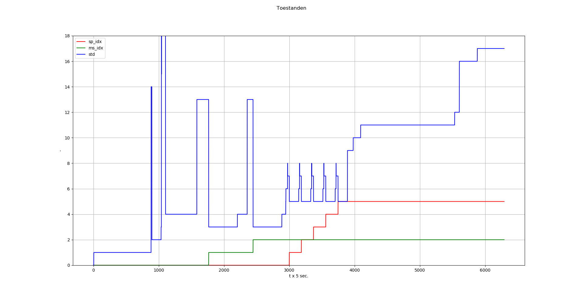
Legend: sp_idx = sparge-index, runs from 0 to maximum number of batch sparges, ms_idx = mash-index, runs from 0 to maximum number of temperature steps, std = actual state of state transition diagram.
Back to Top