ELECTRONICS / HARDWARE Update April 2023
From the many reactions I receive from fellow home-brewers, I understand that, for most of you, it is rather difficult to reconstruct the electronics part. Nevertheless, there are brewers who have an interest in automating their brewing setup. Some of you use ready made components, like a PID controller, a PC IO card or a solid-state-relay (SSR). There's nothing wrong with that approach, but I decided to choose an alternative approach. Playing around with electronics is one of the most enjoyable things for me to do. And since I hold a masters degree in electrical engineering (Eindhoven University of Technology), I also should be capable of designing such a system. Therefore I chose to design the hardware and the software as professionally as possible. The hardware design, presented on this page, should be sufficient for anybody who is familiar with electronics, to rebuild (some of the) parts of my brewing electronics.
In short: the hardware is capable of the following:
- Reading a maximum of 6 temperature sensors: two for the HLT, two for the MLT, one for the boil-kettle and one at the output of the counterflow-chiller
- Reading of the hardware temperature: this is to protect the power-electronics
- Reading a maximum of 4 flowsensors: between HLT and MLT, between MLT and boil-kettle, one at the output of the counterflow-chiller and one between HLT and MLT-return pipe
- Control of 2 electric heating-elements (on 2 separate phases) in both HLT and boil-kettle
- Control of 2 gasburners in both HLT and boil-kettle
- Control of 8 solenoid ball valves at 24 V DC
- Control of 8 actuators at 230 V AC: the pump, a second pump (for the HLT counterflow-chiller), the HLT gasburner and the boil-kettle gasburner and a total of 4 electric heating-elements
Even if you are not really into electronics, maybe you pick up some new ideas along the way. If not, you can also skip this page :-)
This page consists of the following paragraphs:
- 1. Overview / Architectural Design
- 2. PC Interface
- 3. Temperature sensors
- 4. Flow sensors
- 5. Triac/SSR: 230V AC Switching
- 6. Interface for Gas valves / Burners
- 7. Solenoid Ball Valves
- 8. Power-Supply
- 9. Electronics Cabinet
- 10. Assembly and Bill of Materials (BOM)
- 11. Datasheets of Components
1. OVERVIEW / ARCHITECTURAL DESIGN
An architectural design provides an overview of the hardware parts and the various interfaces between them. For the electronics of the brewing system, it looks like this:
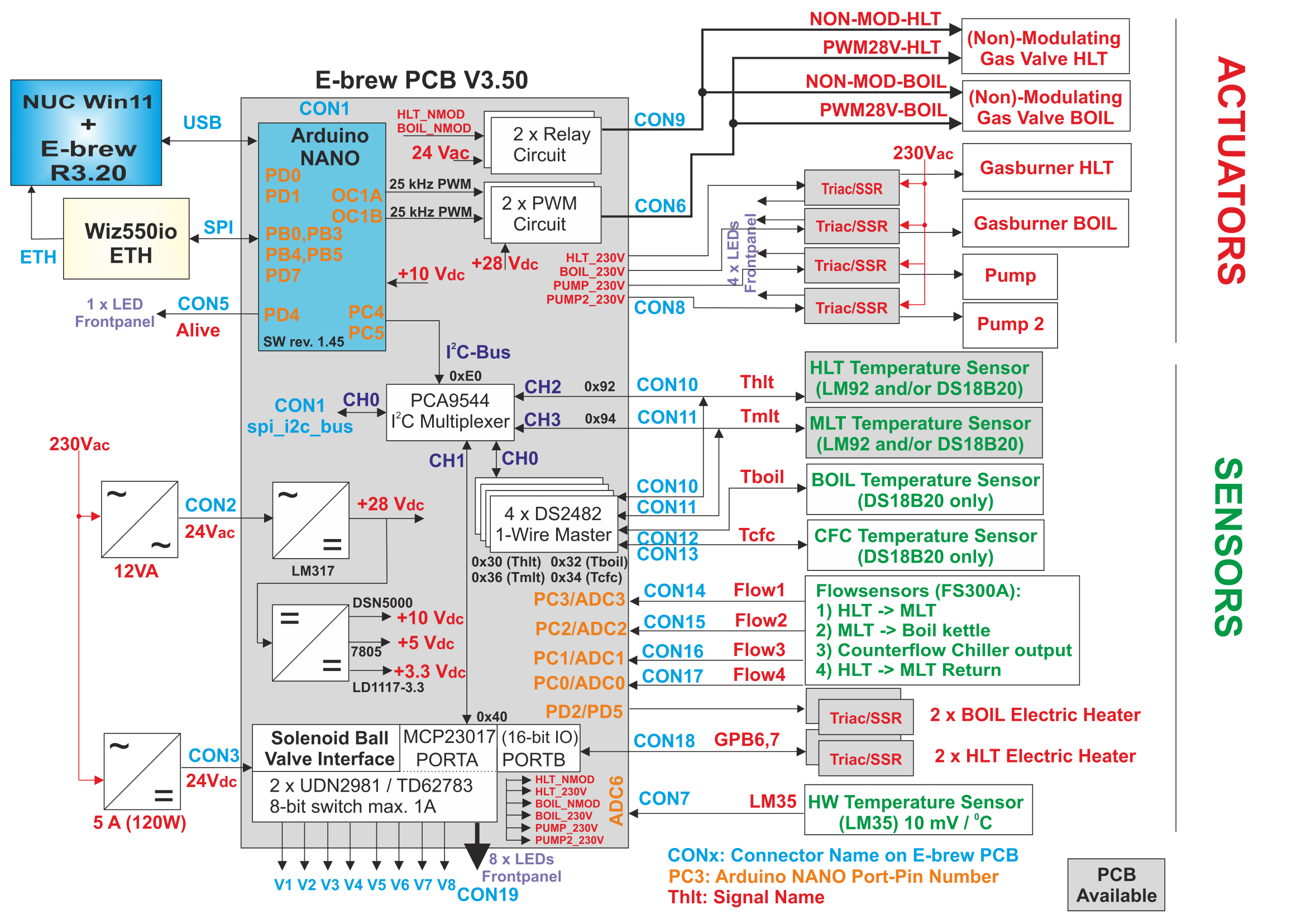
This picture looks complicated at first sight, but I will try to explain things:
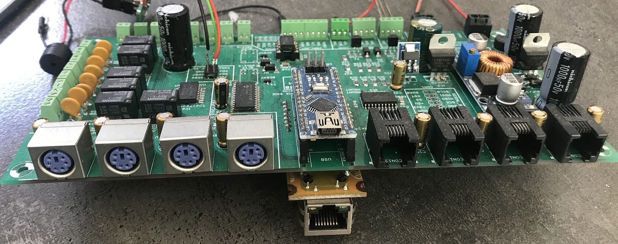
The first component is the PC itself. This is a NUC (small PC) and is connected with an USB cable to the PC-Interface. This USB-cable is primarily used for debugging. Communication between the brewing program on the PC and the electronics itself is done via Ethernet (network).
The brewing electronics is equipped with an Arduino Nano, which is mounted on the main PCB with a dedicated connector. An Arduino Nano is a standard PCB with an Atmel 328P microcontroller. It also generates the signals needed for the I2C bus. This I2C bus is often used to connect ICs to each other and is designed originally by Philips. The advantage of this I2C bus is that there are only two binary signals, a clock line (SCL) and a DATA line (SDA). Every IC connected to the I2C bus, has its own unique address. An even address means a write action, an odd address means a read action. Example: one of the ICs on the main PCB (the MCP23017) has 0x40 (hexadecimal or 64 decimal) as base address. If you want to write to this IC, use address 0x40. If you want to read from this IC, use address 0x41. Most of the electronic components of my brewing setup are connected through this I2C bus, e.g. the two temperature sensors. This means that the two binary I2C wires (SCL and SDA) are also connected to the sensors in the HLT and MLT (together with the +5 Volt and the GND wires). To make reading these sensors as reliable as possible, separate I2C channels are being used. Every sensor has its own unique I2C channel. Multiplexing of the I2C bus (from 1 to 4 channels) is done by a dedicated IC, the PCA9544. Next to reading these I2C sensors, it is also possible to read DS18B20 (One-Wire) temperaturesensors. The HLT and MLT connectors facilitate both types (I2C: LM92 or One-Wire: DS18B20) of sensors.
Despite the complexity of this architecture, the main thought behind all this, is a simple one: read values from sensors (such as temperature and flow) and use this to control the actuators (heating elements, gas-valves, solenoid ball valves). And in order to do all that, you need some electronics!
2. PC-INTERFACE
The communication between the PC and the brewing-electronics is done via an Ethernet connection, but can also be done through the USB port of the Arduino Nano. The Arduino Nano is recognised by Windows (if the standard drivers for the Arduino Nano have been installed) and a virtual COM port is installed, e.g. COM5. All communication between the brewing program (on the Windows PC) and the brewing electronics is done through this virtual COM port. The port settings are 38400,N,8,1, which means: 38400 Baud,no parity bit, 8 data-bits and 1 stop-bit. Both the brewing program and the brewing electronics must have these settings.
After this is done, a simple communication protocol with short commands is used. The following commands (from the brewing-program) and responses (from the brewing electronics) are possible:
- 'A0': Read the value of all temperature sensors. The brewing electronics could respond with: 'T=18.00,65.11,65.02,55.3,20.00'
- 'A9': Read the value of all flow sensors. The brewing electronics could respond with: 'F=84.12,8.15,0.00,0.00'
- 'Bxx yyy': xx is a decimal number that indicates which burner is enabled: 1=modulating gasburner, 2= non-modulating gasburner, 4= electric heating-element 1, 8= electric heating-element 2, 16= electric heating-element 3. All combinations are possible, so a 12 means that both electric heating-elements should be enabled. Furthermore, yyy is a decimal number between 0 and 100. This is the output of the PID controller and indicates the amount of heating power for the Boil-kettle. Command B0 0 disables the burner.
- 'Hxx yyy': same as Bxx yyy, but then for the amount of heating power for the HLT.
- 'L0' or 'L1': Disable or Enable the Alive LED
- 'P0' or 'P1': Disable or Enable the Pump
- 'Q0' or 'Q1': Disable or Enable Pump 2
- 'Vxxx': with xxx being a decimal number between 0 and 255. This is used to open or close the solenoid ball-valves. With V0 all valves are closed, with V1 valve 1 is opened, with V64 valve 7 is opened. Every bit in this number represent one valve. If you wish to open both valve V1 and valve V3 at the same time, then use the command 'V5'.
Besides these commands, a few more diagnostic commands have been made to monitor the brewing electronics itself. By using these simple commands, it is also possible to control the brewing electronics with a PC terminal program. This is convenient during testing and commissioning of the entire system.
A registration in a log-file is made every five seconds of everything sent and received. This is convenient for debugging purposes. A little excerpt from such a log-file looks like the following:
File opened: 03.04.2023 09:53:12 Ethernet: 192.168.1.11:8888
W12.733[S0] R12.736[S0] R12.736[E-Brew V3.0 rev.2.02]
W12.843[R0]
W13.343[L1]
W13.844[L0]
W14.144[H12 0]
W14.144[B12 0]
W14.243[V0]
W14.243[P0]
W14.343[L1]
W14.843[L0]
W14.943[A0] R14.949[T=0.00,22.63,23.97,23.94,23.94,21.77,23.63]
W15.144[H12 0]
W15.145[B12 0]
W15.244[V0]
W15.244[P0]
W15.344[L1]
W15.443[A9] R15.447[F=0.00,0.38,0.32,0.00]
W15.843[L0]
W16.144[H12 0]
W16.145[B0 0]
W16.244[V0]
W16.244[P0]
W16.343[L1]
W16.843[L0]
W16.944[A0] R16.949[T=0.00,22.61,23.97,23.92,23.94,21.75,23.63]
3. TEMPERATURESENSORS
My first design with temperature sensors involved a LM35, which increases its output voltage with 10 mV for every °Celsius. That voltage was amplified and then being read by an AD-converter. The disadvantage of this approach was the relatively large number of ICs needed.
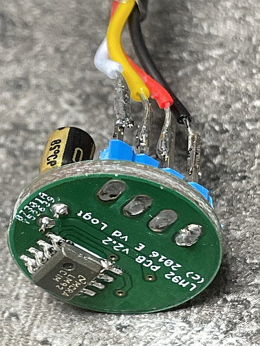
My current design uses a 12-bit + sign bit digital temperature sensor, the LM92. This sensor has all necessary electronics already on-board. The only thing still needed, is a connection to the I2C bus. The 12-bit digital code that is read from the device, is the digital representation of the actual temperature. The LM92 has an accuracy of 0.33 °C. The biggest problem with this device is to mount it reliably in your kettles. I solved this by placing it on a small printed circuit board, glue that at the bottom of a copper pipe, and then cast it with clear plaster resin (with thanks to Marco Mantel for the brilliant idea!).
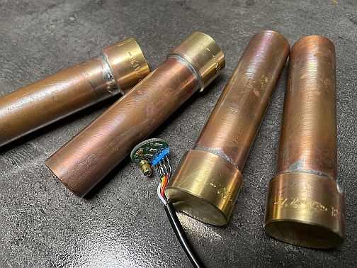
The picture shows the LM92 soldered to a small printed circuit board, next to a copper pipe already filled with plaster resin. It takes a couple of weeks before the plaster resin has hardened. But then you do have a waterproof construction, which can be mounted inside the kettles.
The address of the LM92 on the I2C bus is adjustable with 2 pins A0 and A1. You can either ground these pins (a logic 0) or connect to the +5 V (logic 1), which creates a total of 4 possible addresses. Because every kettle has its own I2C connection, I use address 0x90/0x91 (A1=0, A0=0) for every sensor (although all four addresses are accepted by the brewing hardware).
I have been experimenting with temperature sensors for a couple of years, but these LM92 are absolutely perfect. You obtain a digital code directly, there's no need for a separate conversion/calibration (which you do need with a PT100 element), no additional electronics are required, they are very reliable and they always work! For more information about construction, including design-files and source-code, please read my blog: http://wordpress.vandelogt.nl/?p=13
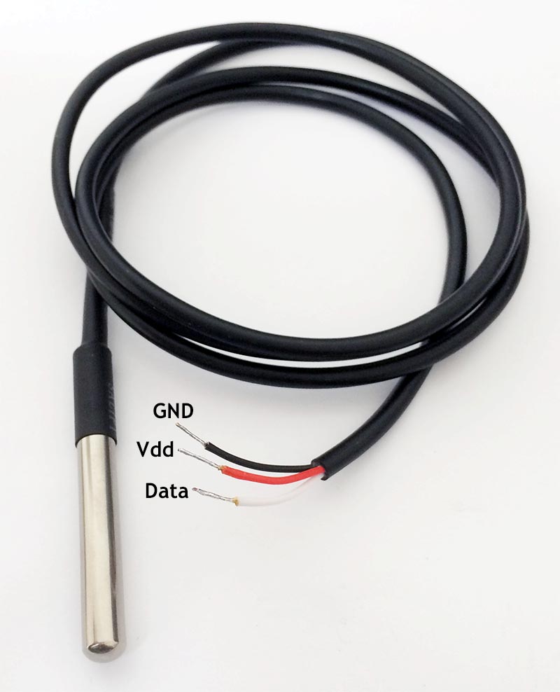
Have we now covered everything w.r.t. temperature sensors? No, lots more to tell: many fellow homebrewers use One-Wire temperature sensors (DS18B20). Why? Because this sensor comes in a waterproof containment (stainless steel) and are dead cheap on Aliexpress. By mounting these sensors inside your kettles, you don't have to mess around with plaster resin (which we needed to do for the I2C LM92 sensors).
The one-wire protocol is a completely different communication protocol than the I2C bus. But, since not all connections were in use at the connectors (CON10 and CON11) for the temperature sensors, it was relatively easy to add one wire for the one-wire protocol. More difficult is the control and reading part of the one-wire sensor: it works on a microseconds base, so you need to have accurate timing. Many people use a standard library from the Arduino for this. So a software solution. For reasons of reliability I chose for a hardware solution here.
There is a nice little IC (DS2482-100) available that connects to the I2C bus and sends out a one-wire signal. You could therefore call it an I2C to one-wire bridge. This IC is present four times in the brew-electronics, one for every temperature sensor (HLT and MLT temperature). This seems like overkill, since only one IC would do for a one-wire solution. The big advantage with 4 ICs is that you can hot-swap the temperaturesensors. Disconnect one and reconnect another: the brew-electronics detects this and reads out the new temperature value.
Since the HLT temperaturesensor is essential for temperature control, there are two sensors mounted inside the HLT: one is a I2C LM92 and the other a One-Wire DS18B20 sensor. The brewing program can be adjusted so that both sensors can be used independently. But they also can be used for HLT temperature measurement. In this case, both values are averaged and the result is used as the HLT temperature.
If either one of these sensors fail, the other one is used automatically as the HLT temperature measurement.
The same is done for the MLT: use two sensors independently of each-other or use 1 sensor (in this case the I2C LM92 one) as MLT temperature measurement and the other for another temperature measurement, such as in the MLT return pipe. This option is used in the current brewing-system.
There are two additional One-Wire sensors (One-Wire DS18B20) and they are used to read the temperature of the boil-kettle and the temperature at the outlet of the counter flow chiller (during cooling, after boiling).
Back to the Top of the Page4. FLOWSENSORS
Measuring volumes in a kettle can be done in a couple of different ways. The most used ones are with a pressure-transducer of with a flow-sensor. I now solely use flow-sensors, because they have many advantages over pressure-transducers.
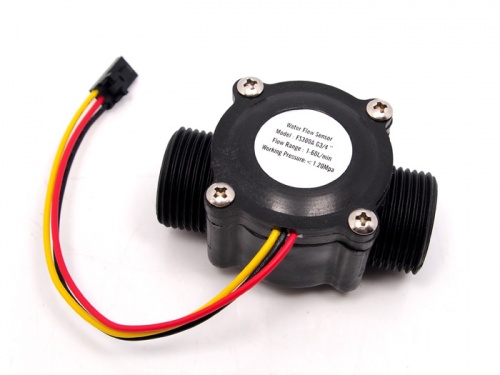
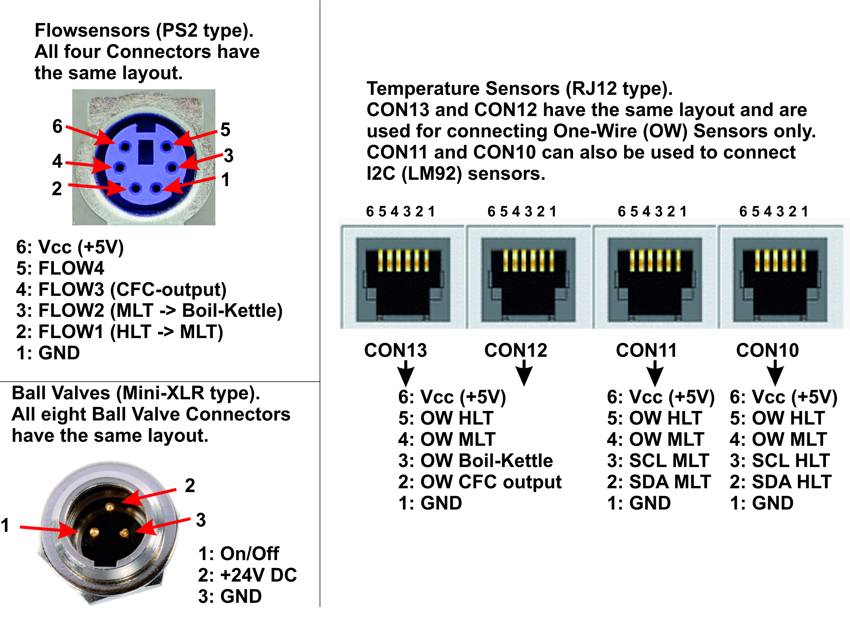
a Flow-sensor is mounted in a pipe, e.g. a pipe mounted between two kettles such as the HLT and the MLT. The flow-sensor has a little wheel inside that starts to turn when a fluid passes through. The signal from these flow-sensor are connected to connectors CON14 to CON17. These signals are then read in by the Arduino Nano, which counts the number of pulses. The flow-sensor used here is a FS300A flow-sensor and delivers approximately 330 pulses per litre of fluid. With this it is possible to accurately measure the number of litres passed through the system. In the current setup four flow-sensors are used: one between the HLT and the MLT and one between the MLT and the boiling kettle. A third one is mounted at the outlet of the counter flow chiller, so you can determine the amount of litres transferred into the fermentation bin. And the fourth flow-sensor is mounted between the HLT heat-exchanger and the MLT return pipe to determine the actual wort flow during mashing.
All four flowsensors can be calibrated in the brewing program. This is done by adding or subtracting a percentage from the flowsensor value. If, for example, the flowsensor returns a value that is 7 % too high, the corresponding parameter is set to -7 %. This makes it possible to obtain an accuracy within 0.1 L.
Back to the Top of the Page5. TRIAC / SSR: SWITCHING 230V AC
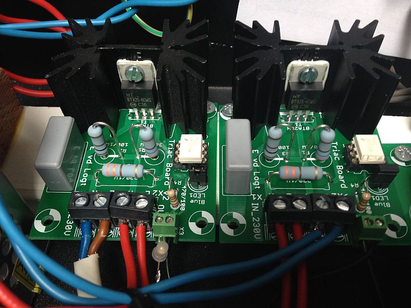
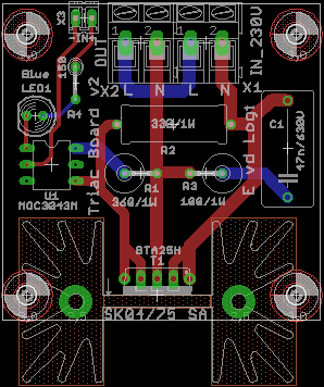
Switching parts that work with 230 Volts AC (pumps, gasburners and electric heaters) is done by a separate printed circuit board (the 'Triac PCB') in the electronics cabinet. The picture show two Triac PCBs, the one on the left is for the HLT gasburner, the one on the right is for the pump. A Triac PCB receives a signal ('HLT_230V' and 'Pump_230V') from the brewing electronics. With this, the heating element and the pump are switched on or off.
The most common used method by home brewers is to use a ready-made Solid-State Relay (SSR). It is not too difficult to create your own SSR, because there are special power electronic components available, which can do the job. A good example is the Triac. The brewing electronics uses a BTA25H. This Triac is capable of switching up to 25 A at 600 V. This is more than adequate for our purposes. The advantage of this Triac is that it's back is isolated! So if you mount this Triac to a heat-sink, the heat-sink is not connected to the mains (which is a good thing).
The Triac for the heating element has its own cooling plate, to which I glued a LM35 temperature sensor. The Triac temperature is controlled continuously by the brewing program. If the temperature increases above a predefined level, the Triac is switched off. NOTE: the picture above shows the pcb with a small heat-sink (and no LM35). This is sufficient to switch a pump, but it is inadequate for switching a 3 kW heating element! For that, you need a larger heat-sink!
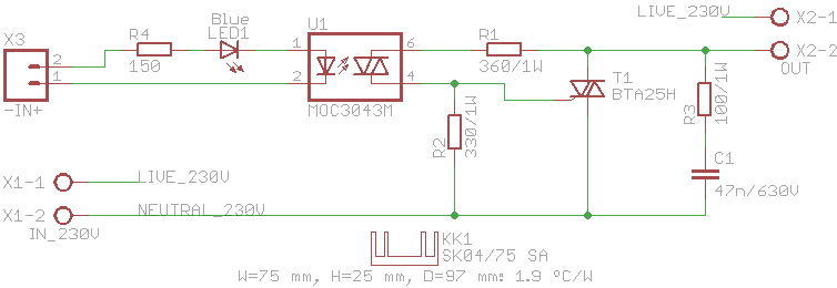
Most of the intelligence w.r.t. switching is done using a special IC, the MOC3043. This IC contains a zero-crossing circuit. It means that the Triac is switched on, when the AC voltage crosses 0 Volts. This assures a smooth switching behaviour, leading to almost no disturbances. Furthermore, the IC also contains a galvanic isolation: if there's a problem in the power electronics, then this does not result in additional damage in the electronics and/or the PC. The last picture shows the schematic and the PCB layout of the Triac PCB:
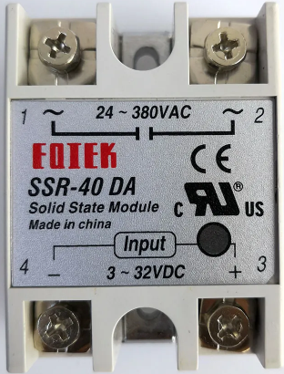
Over the last few years, standard Solid State Relays (SSR) have become so cheap and reliable, that it is not worth anymore to build one your own. Best thing to do now is to buy a standard SSR at Aliexpress.
Back to the Top of the Page
6. INTERFACE FOR GAS-VALVES / BURNERS
One of my neighbours is a plumber and for every new central heating boiler he installs, and old one is removed. These old central heating boilers are then given to me. Such a central heating boiler contains, next to a decent burner, a gas-valve. Since early 2005 I switched over entirely to these gas-burners, since they have far more power than the ones I used. These gas-valves come in two flavours:
- Non modulating: the gas-valve is either ON or OFF, a position in between is not possible. These burners are controlled (in general) with a 24 V AC voltage. Voltage present means that gas-valve is open, no voltage present means gas-valve is closed.
- Modulating: these gas-valves are controlled by a pulse width modulated (PWM) signal. For this, we need a bit more electronics than with a non-modulating gas-valve. The gas-valve can be set to any value between 0% and 100%. This is ideal for our brewing setup, because the PID-controller provides an output signal that is a percentage between 0% and 100%).
6.1 Non-modulating gas-valve
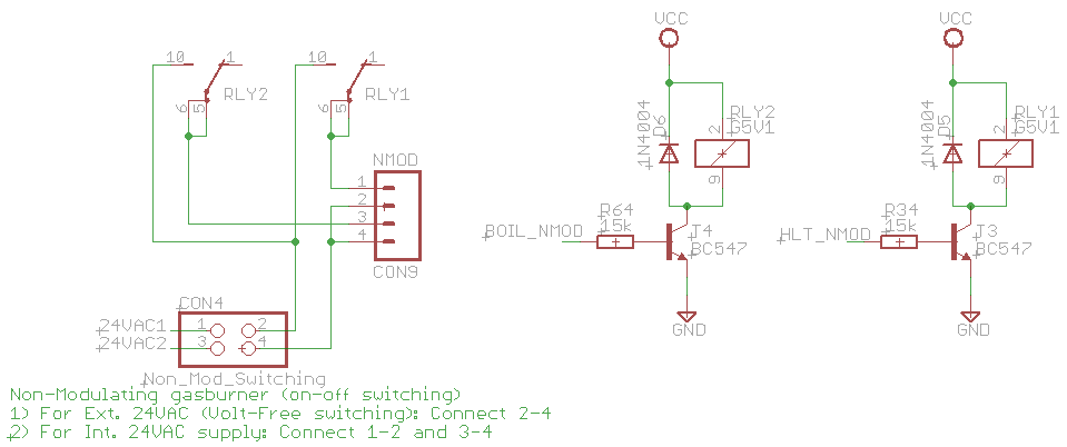
A non-modulating gas valve only needs to have a 24 V AC voltage. The schematic shows how this is realised (this schematic is actually a part of the entire brewing electronics PCB). CON4 is a jumper block that is connected to 24 V AC. This is used to control the proper configuration. If a gas-valve already has a voltage supply, it only needs a voltage-free switching contact. The brewing electronics does not have to supply 24 V AC. If this is the case, then pins 2 and 4 of CON4 need to be connected to each other.
If the gas valve DOES need a 24 V AC signal (which is the situation for most non-modulating gas-valves), the brewing electronics can also supply this. In this case, pins 1 and 2 need to be connected to each other AND pins 3 and 4 needs to be connected to each other. The actual switching of the gas-valve is done by relays. The Arduino Nano generates two signals BOIL_NMOD and HLT_NMOD, which are the signals for the boil-kettle and the HLT. The relay is controlled by a NPN transistor, a BC547. The output signal is present at connector CON9, which should be connected to the non-modulating gas-valves.
The output of the PID controller in the brewing program is a percentage (between 0% and 100%). The is the amount of power needed. This signal can not be used directly to control the relay. If more power is needed than a predefined threshold value (e.g. 40%), the relay is switched on. The relay is switched off when the PID controller output is lower than another predefined value (e.g. 35%). This hysteresis prevents that the burner is switch on and off again within a short time period.
6.2 Modulating gas-valves
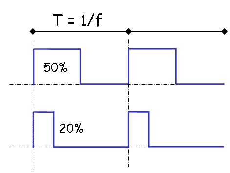
A modulating gas-valve is controlled by means of a PWM signal, as stated before. The picture shows a PWM signal. Striking for a PWM signal is that the frequency of the signal is fixed. Most gas-valves expect a PWM signal with a frequency f of about 25 kHz (the period time T is then 40 microseconds). The amplitude (height of the signal) is often a value between 24 and 28 Volt.
For a pulse width of 50 %, the duty-cycle of the signal is the same (on-time is the same as off-time), for a pulse width of 20 %, the signal is high for 20% of the period time and low for 80% of the period-time. A PWM signal of 100% always high, whereas a PWM signal of 0% remains low all the time.
To control a modulating gas-valve, we need the following:
- A power supply that delivers 24..28 V DC (besides the power supply for the electronics)
- An oscillator circuit that produces a 20 kHz square wave signal
- A circuit that generates two PWM signals: one for the HLT and one for the boil-kettle
The use of an Arduino Nano is convenient in this situation. For a microcontroller, such as the Atmel 328P, it is relatively simple to generate such a 25 kHz signal. A separate oscillator circuit is not needed, we simple need to program a Timer (Timer 1 in this case) of the ATmega 328 microcontroller. The PC brewing program delivers an output signal from the PID controller with the Bxx yyy and the Hxx yyy commands. This is used by Timer 1 of the microcontroller. Timer 1 is configured in such a way that it generates a 25 kHz square wave signal with a duty-cycle equal to the PID controller output signal. The outputs of Timer 1 (OC1A and OC1B) are the input signals for the PWM circuit. These signals are called HLT_PWM and BOIL_PWM in the schematic below. This schematic shows the PWM circuit, which is part of the entire schematic of the brewing-electronics.
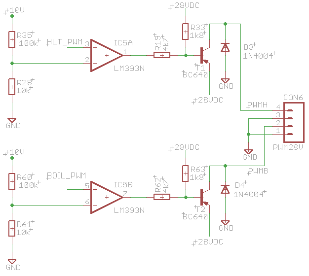
The Power-Supply section has already generated a 28 V DC voltage. This is now connected together with the PWM signals to a comparator with an open-collector output (the LM393). The open-collector outputs of the LM393 can be connected directly to the 28 V DC voltage. The PNP transistor BC640 controls the gas valve itself. Connector CON6 sends these signals to the modulating gasvalves.
Back to the Top of the Page7. SOLENOID BALL VALVES
The solenoid ball valves need 24 V DC in order to switch them on. Switching of the solenoid ball valves is directed by the State Transition Diagram. The first component of the hardware interface for these solenoid valves is a 16-bit I2C IO expander, the MCP23017. This IC is used because the ATmega328 microcontroller doesn't have sufficient free IO pins available. Every port pin of the MCP23017 controls 1 solenoid valve. Such a port pin is connected to one of the inputs of a TD62783 Darlington Transistor Array. This IC contains 8 Darlington transistors which can switch up to 0.5 Ampère. This is more than sufficient for the solenoid ball valves, which only draw current during switching.The schematic of the solenoid valve interface is given below. It is part of the entire schematic of the brewing electronics PCB.
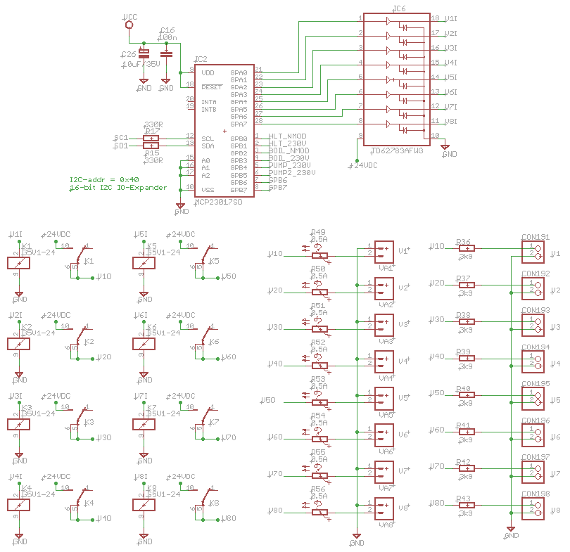
The only thing not covered in the schematic are the resistors R49 until R56. These are resettable fuses or PTCs. They have a low resistance at a current of 0.5 Ampère, but this resistance greatly increases when the current gets close to 1 Ampère. The increased resistance limits the maximum current possible. In case of a short-circuit these PTCs hopefully prevent permanent damage to the electronics. In industrial PLCs, the outputs are often protected with these devices. So it is a good thing to add them here too.
Back to the Top of the Page8. POWER-SUPPLY
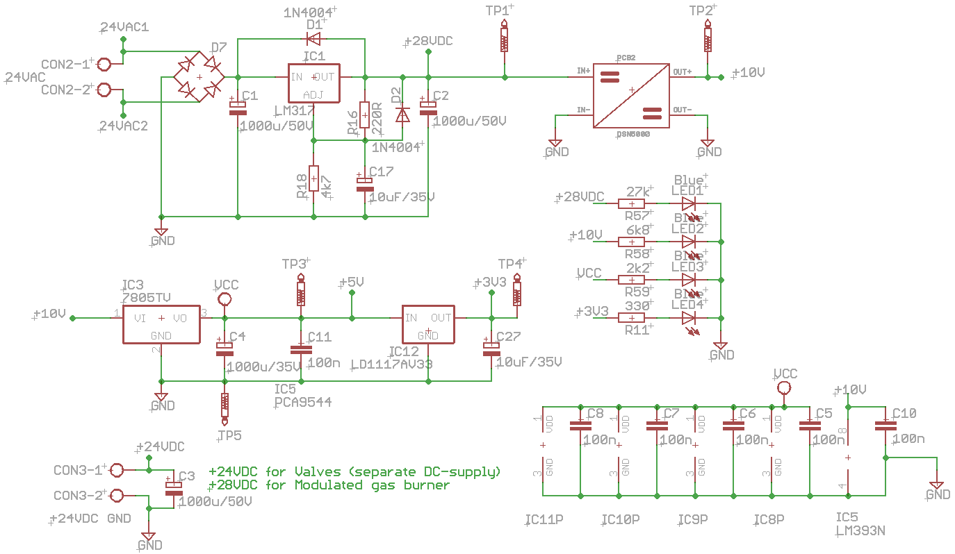
The power-supply section of the brewing electronics is worth mentioning here, because different voltages with different power are needed. The architectural design shows a number of transformers:
- A 230V/24V transformer with a power rating of 10 VA. This one is used to generate a 28 Volt DC voltage. This voltage is needed for the modulating gas burner. A standard LM317 is used for the actual generation of the 28 V DC voltage. The 28V DC is also the input for a DC-DC converter, which generates 10 V DC from it. The 10 V DC is one of the voltages needed, it is also used to generate 5 V DC (with a 7805 IC). So in total, the 24V transformer generates 28 V, 10 V and 5 V DC.
- A Switched Power-Supply capable of delivering 5 A at 24V DC (or 12V, see the text-box above). This is a standard part which I bought on Aliexpress. Just look for '24V switching power supply' and you find several power-supplies. For the price, you can't make it yourself. The 5 Ampère rating is more than enough to power the solenoid valves, which draw a maximum of 1.5 Ampère.
The power-supply schematic (which is part of the entire schematic of the brewing-electronics PCB) is given here as reference:
 Back to the Top of the Page
9. ELECTRONICS CABINET
All PCBs are mounted inside a cabinet. This is a standard metal case from Hammond. Sizes are 17" (43.2 cm) width, 4" (10.2 cm) high and 10" (25.4 cm) deep, typenumber is Hammond 1441-33BK3. The bottom plate has type number 1431-30BK3. To give it a professional look, I made faceplates for both the front and the back. Excellent service from Tube-Town. These faceplates are shown in the picture below:
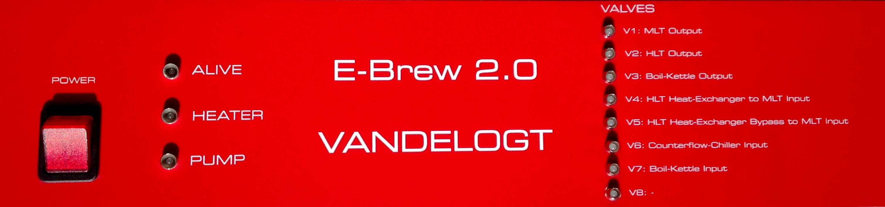
The front has the following connections:
- Power switch. Main power switch for the electronics.
- Alive LED: the ALIVE indicator, blinks 1 time per second. This is a visual indicator for the correct operation of both hardware and software.
- Heater LED: LED is on when the heating element of gas-burner is energised.
- Pump LED: LED is on when the pump is switched on.
- LEDs for valves V1 until V8: if a LED is on, the corresponding solenoid valve is open.
At the backside the following connectors are seen:
- Four 230 Volt IEC female connectors (female): one for enabling the HLT gas-burner, one for the boil-kettle gas-burner and two for the two pumps.
- Connectors (RCA) for a modulating gas-valve and for a non-modulating gas-valve
- Four RJ12 connectors for the temperature sensors in HLT, MLT, boil-kettle and the counterflowchiller output.
- USB-Interface for the connection with the PC.
- RJ45-Interface for the connection to the home-network.
- Four PS/2 connectors for the flowsensors.
- Eight Connectors (Mini-XLR) for solenoid ball valves V1 until V8.
- 230 Volt mains power (IEC male).
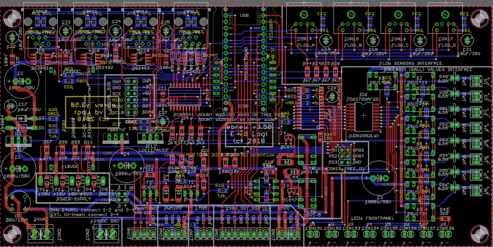
Most of the subparts of the brewing-electronics PCB are now already explained. The PCB itself is fabricated by JLCPCB) and looks as shown here:
Here is another picture of an empty PCB (bottom) and a completely assembled PCB (top) with the Arduino Nano mounted on top:
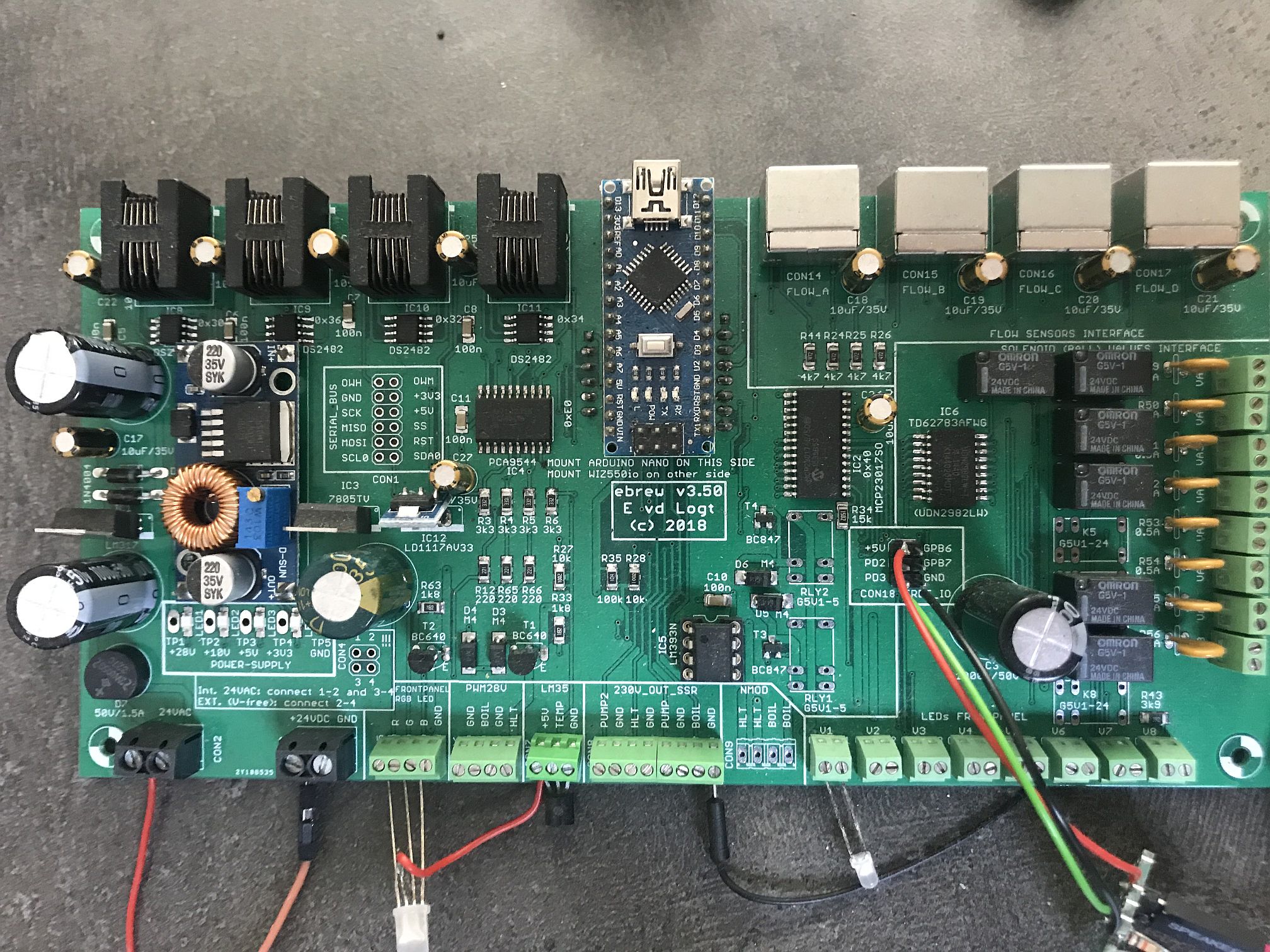
The quality of these PCBs is very good, especially the silkscreen (printed white text) helps you a lot in assembling this PCB. Finally another picture of the front of the PCB, showing all connectors clearly:
If you want to make the sensors with the cables and connectors, the following picture shows you how to make these:
 Back to the Top of the Page
10. ASSEMBLY AND BILL-OF-MATERIALS (BOM)
I get lots of requests from other home-brewers worldwide how they can create a similar automated brewing system. A Bill of Material (BOM) is a good starting point for this. Although it is impossible to list all different kinds of configurations, I can give you a Bill of Materials for a standard setup, which is in my case the following:
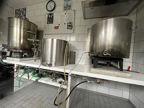
- HERMS system with three kettles.
- Four flow-sensors.
- Six temperaturesensors: two inside the HLT (1 One-Wire and 1 I2C), two inside the MLT (1 One-Wire and 1 I2C), one mounted inside the boil-kettle and one mounted at the outlet of the counter flow chiller.
- Two modulating gas-burners, one mounted underneath the HLT and one underneath the boil kettle.
- Two heating-elements (one inside the HLT and one inside the boil-kettle). Each heating-element has two separate heating-elements.
Bill of Materials: General Items
- Three stainless steel kettles with pipes welded in the right places. This is something you have to find or construct yourself. Those kettles are not standard components.
- Two Iwaki MD-30R pumps. Not too difficult to find at second-hand sites. Most pumps are fine, as long as they are magnetic pumps.
- Gas-burners. Special components, different for every country. Certainly not a standard component, so go find yourself something similar. My gas-burner is a V4600N from Honeywell, coil type is the V7335A and it is taken from an AGPO Ferroli 1324T natural gas burner kettle.
- Two Counterflow chillers. Heat exchangers are easy to find, otherwise create one yourself, as I did.
- Solenoid ball valves: 6 pieces from ebay store Valves4Projects. Search for: Ehcotech M21SE-1/2-E3BW motorized ball valve.
- Temperature sensors: 4 pieces DS18B20 one-wire temperaturesensors and 2 I2C LM92 temperaturesensors. The DS18B20 sensors are easy to find on Aliexpress (search for: ds18b20 waterproof). Tip: order 5 pieces.
- Flow sensors: 4 pieces FS300A flow sensors with thread diameter G3/4". Components are easy to find on various sites.
- Solid State Relays (SSR): 6 pieces, of which 4 have a heatsink. The ones with a heatsink are meant for the 2 2-phase heating elements. The two SSRs without a heatsink control switching of the gasburners.
- Various connector plugs (RJ12, PS2) to connect the sensors to the brewing-electronics.
- Lots and lots of copper pipes and couplings.
Bill of Materials: Brewing-electronics
Without doubt the most complex piece of electronics in the system. You can find a detailed component list below. Component prices are just an indication (price-level is from July 2015). Many of these components can be ordered on Aliexpress for a fraction of the price listed here. So it really is worthwhile to do a bit of shopping there.
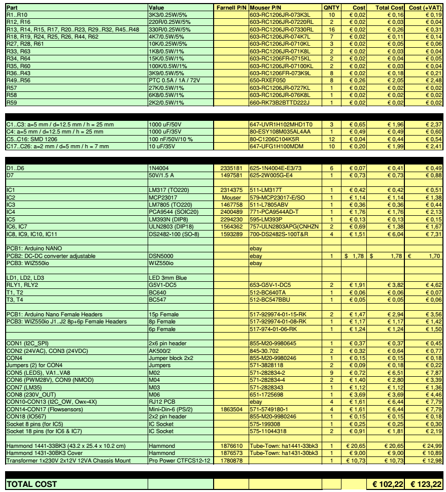
If your soldering skills are not really up to par, you can also order a PCB directly from me, with the SMD devices already soldered in place. If you would like to have a completely soldered and tested PCB: that might be possible too. If you want to do it all yourself: take proper ESD measures! An anti-static wrist-band is the very minimum for this.
Bill of Materials: Cabinet
Last Bill of Materials is for the cabinet of the electronics, together with all jacks and plugs.
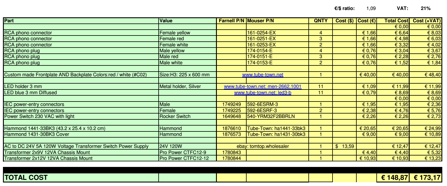
Not listed here but also needed: lot of wires, isolated, non-isolated and in various gauges.
Back to the Top of the Page11. DATASHEETS OF COMPONENTS
The various ICs used in the electronics brewing setup are listed here with their datasheets:
- BTA25H, Triac (600 V, 25 A) Isolated
- LM393, Opamp / Comparator with open-collector
- LM35, Analogue temperature sensor (10 mV/°C)
- LM92, Digital temperature sensor (12-bit + sign bit, 0.33 °C accuracy, I2C)
- DS18B20, Digital temperature sensor (11-bit + sign bit, 0.50 °C accuracy, One-Wire)
- MCP23017, 16-bit I2C IO-port expander
- MOC3043, Triac driver with galvanic isolation and zero-crossing detection
- PCA9544, 8-bit Multiplexer (4-channel) for I2C-bus
- TD62783 8 ch High Voltage Source Driver