SOFTWARE
A fully functional software version of the PC-program can be downloaded from here (ebrew_Qt_exe.zip file, v3.20). In order to have a complete brewing system, you also need the brewing hardware with the latest firmware.
Although a significant amount of hardware / electronics has been created, it is useless without any software controlling it. When I started with the design of my system I wanted to have full flexibility. I could go for a microcontroller based design, with embedded software in it, so you would not need a PC. But I have various PCs hanging around in my house, so why not use one of them (in a network configuration) for controlling your home brewery? In this way, I have lots of flexibility. If I want some new behaviour built into my brewing program, I make an update, test it and distribute it over the network to the PC in the brewery.
This particular setup has worked for years without any problem. The hardware was connected to the PC by means of a parallel port (or printer port). With the transition to a new hardware platform, this was upgraded to a (nowadays) more common USB connection. And then the set-up with the microcontroller becomes interesting again. Lots of old functionality, like the generation of the PWM signal, is easy to realize for any microcontroller. So the amount of hardware components can be reduced, as a result of this. The latest version of the hardware uses an Ethernet connection for its communication and the USB connection is only used for debugging purposes. This microcontroller also needs software, which we call firmware, to distinguish it from the PC-software.
What shall we use as programming language for both systems? Well, for the firmware this is quite clear: up until 2022 the Arduino Nano was used, for which I use Atmel Studio and the C programming language, see github.com/Emile666/Brew_Arduino for the source-files. The latest version of the brewing hardware doesn't have an Arduino Nano anymore, but is equipped with an STM microcontroller, the STMM8S207, which is a 64 pin LQFP device. The firmware for the STM8S207 is written with IAR Embedded Workbench - STM8 series, also in the C programming language, see github.com/Emile666/Brew_HW_Stm8s207 for the source-files. For embedded systems you almost never have a decent alternative for C, so this is the preferred set-up.
For the PC-program it is less clear because of the large variety of programming languages available. I do not really like the new programming languages like Java and C#/.Net. I typically write my programs in the C programming language, but I definitely needed a nice front-end GUI (windows, menus, all the stuff) for the PC program and C in itself is not really suitable for that. The solution however was to use the C++ programming language, which is object-oriented and you can even use your existing C libraries (if needed) and build a nice looking program.
The PC application was initially built using Borland C++ Builder and this setup was used until 2017. C++ Builder became obsolete and an alternative needed to be found. The current PC application is developed with the Qt development environment, see www.qt.io), again with C++ as the programming language.
So the configuration is chosen, the programming language is set. What to do next? Well, I can tell a bit about the internal structure of my brewing program (which I called e-brew! by the way, which stands for electronic brewing). This page consists of the following paragraphs:
- 1. The Graphical User Interface (GUI)
- 2. Overview / Software-Architecture
- 3. The Scheduler
- 4. The State Transition Diagram (STD)
- 5. Firmware for the Arduino Nano / ATmega328
1. GRAPHICAL USER INTERFACE (GUI)
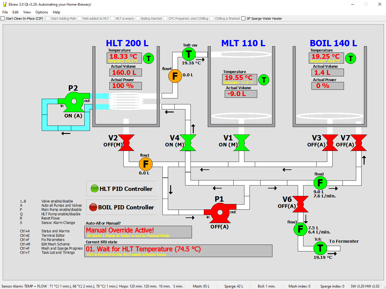
To shield the complexity of the software for the use of the program, a decent Graphical User Interface (GUI) is needed. This GUI defines the look and feel of the program and makes sure that everything is running smoothly during brewing. After inital power-up, the main-screen is shown, of which a screenshot is given at the top of this page.
All necessary information for a brewing day is shown or can be adjusted, which is ideal if you want to check certain values:
- Setpoint (SP) and actual temperature values of the HLT kettle, the MLT kettle and the boil kettle. Also the temperature at the exit of the counterflow chiller is shown. The screenshot shows and actual HLT temperature of 18.33 °C and an actual MLT temperature of 19.55 °C. The desired (setpoint) temperature for the MLT is set here to 71 °C and is set to 74.5 °C for the HLT (this screenshot is taken during a debugsession, so values are not from an actual brewing-session).
- Menubar with checkboxes. These checkboxes can be checked to indicate that a certain action is completed, for example "Malt added to MLT".
- Current state: This label shows the current state of the brewing system. The current state in the screenshot is "01. Wait for HLT Temperature (74.5 °C)".
- Actual Power of the kettles: the screenshot shows that the HLT burners are set to 100 % (full power) and the burners for the boil kettle are set to 0 % (off).
- Actual Volumes of the kettles: the screenshot shows a volume for the HLT of 160.0 L, for the MLT this is -9.0 L and the boil-kettle contains 1.4 L. The volumes are not read in directly from the hardware, they are determined using the flowsensor values. Everything that runs from the MLT, decreases the MLT volume and is added to the boil-kettle volume.
- Flowsensor values: there are four flowsensors present in the brewing-system. The first sensor is mounted between the HLT and the MLT, the second flowsensor is mounted between the MLT and the boil-kettle, the third flowsensor is mounted at the output of the counterflow chiller and the fourth sensor is mounted between the HLT heat-exchanger output and the MLT return pipe. These values show the total amount of liters passed through these sensors and the flow rate (number of liters per minute). In this case the first and fourth flowsensor have not seen any fluid passing through them, sensor 2 is now active (green) and reads 9.0 L total with a flow rate of 7.6 L per minute. Flowmeter 3 sees an actual flow rate of 6.4 L per minuut. These values are from a debugsession with values imposed (in fact: flowsensor 2 can not see an actual flow in a real brewing session, because valve V7 is still closed and the pump is off).
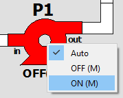
- Pump status: three options are possible here: "Auto", "Pump Off (M)" and "Pump On (M)". These options can be selected by clicking with the right-mouse button on the pump object. If the option "Auto" is selected, the brewing program (in particular the state transition diagram) will switch the pump on and off. The automatic switching can be overruled by selecting one of the manual options, which is indicated with an (M) symbol near the pump. The screenshot at the top shows that pump P1 (the main brewing pump) is set to Automatic and is currently switched off, while pump P2 (which takes care of circulating water inside the HLT) is set to Automatic as well and is currently switched on.
- Valve status: every valve can be set to three states (same as for the Pumps): "Auto", "Off (M)" and "On (M)". The screenshot shows that valves V3, V6 and V7 are set to Auto and Closed. Valve V2 is on Manual and Closed, valves V4 and V1 are also set to Manual, but they are opened.
- Status bar: the status bar shows information such as alarm settings (the brewing hardware will beep when there's either a temperature or flowsensor malfunction), the current mashing scheme (temperatures and times), the amount of mash- and sparge-water, the current index in the mash and sparge scheme and the version numbers (which is now R3.20 for the PC-program and R2.02 for the firmware of the brewing hardware).
- There's also a list of shortcut keys. Any nummer pressed opens or closes the corresponding valve, with an 'A' every manually set valve or pump is set again to Automatic. This is convenient when you are in manual control and you want to switch back again to Auto (without forgetting anything).
If any of the values read is wrong, or when there is no communication, the corresponding colors of the sensors turn Red. The screenshot shows that all temperatures are read correctly here (all green). Also the flows of sensors 2 and 3 are read correctly too.
1.1 FEATURES OF THE PC BREWING PROGRAM
The menu-bar of the PC brewing program contains the following menu-items:
- File -> Exit: exit brewing program, all electronics is switched off and communication with hardware (Ethernet of USB) is closed.
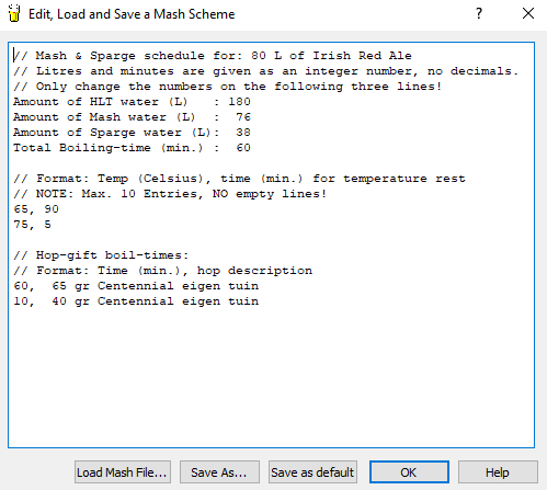
- Edit -> Mash Scheme... (Ctrl+M): with this option, up to 10 temperature-time pairs can be entered. Specific times and temperatures for a mash scheme can be entered, also the hop-gift scheme is specified here and the amount of mash- and sparge-water. Best thing to do is to have a separate mash scheme file for every particular beer recipe.
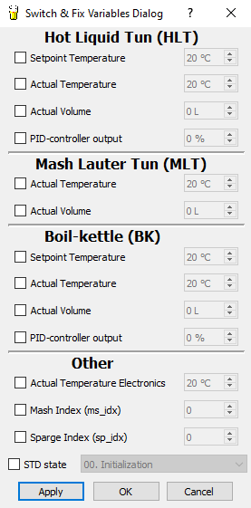
- Edit -> Fix Parameters... (Ctrl+F): every relevant parameter can be given a value. Example: normally, the HLT temperature is read from the digital temperature sensors, but suppose that you want to set it (e.g. for testing purposes) to some other value, thereby overruling the value from the sensor. You can use this menu option to fix a parameter to a certain value. If you release the value again, brewing program will take over again. This screen is only useful during testing and debugging, for a typical brewing session, this screen is not needed.
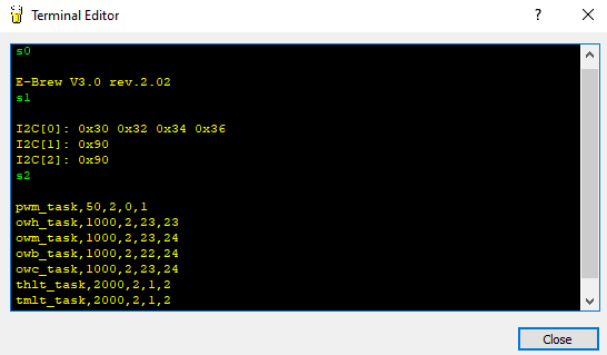
- Edit -> Terminal Editor (Ctrl+E): another screen that is not needed during a regular brewing session. A terminal editor is opened, with which you can send commands directly to the brewing hardware.
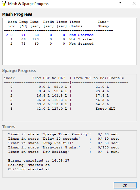
- View -> Mash/Sparge Progress (Ctrl+P): this screen shows the status of all mash, sparge and other timers. It gives detailed information how long a certain rest will last, which rests are done and what the batch sparging scheme is.
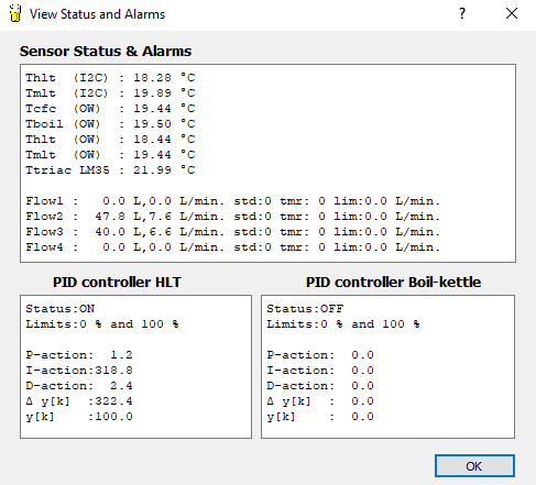
- View -> Status and Alarms (Ctrl+A): this screen shows the status of all sensors connected to the brewing hardware (both temperature and flow). If a sensor is not working, this screen is used to diagnose that. It also shows the internal values of the PID-controllers, which is convenient when dialing in the PID-controllers.
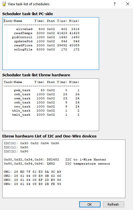
- View -> Task-list and Timings (Ctrl+T): this screen shows all software related tasks and the actual and maximum amount of time they need. This is shown for both the PC application as for the firmware of the brewing hardware. There's also an overview of the hardware devices found, both ICs and sensors. The screenshot below shows four I2C-to-One-Wire bridges (DS2482 IC) and two connected LM92 temperaturesensors. There are also four One-Wire temperaturesensors found.
- Help -> About...: shows the current revision number of the PC application.
- Help -> About Qt...: shows some general info about the Qt environment.
- Options -> System Settings...: this dialog screen consists of three parts: 'Heater Options', 'Communications' and 'Brew-Kettle Volumes'. All settings done here, are saved into the Windows Registry. The next time the PC application is started, these values are retrieved again from the Registry.
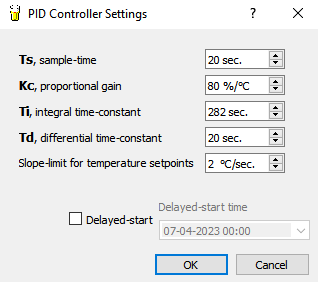
- Options -> PID Controller Settings...: various control setting for the PID controller can be entered here.
- Options -> Brew Day Settings...: this dialog schreen consists of four parts: for Mashing, for Sparging, for Boiling and for Cleaning (Clean-in-Place). Most settings here are self-explained, but also contain a hint-text.
- Options -> Measurements Settings...: this dialog screen consists of two parts, one for the temperaturesensors and one for the flowsensors.
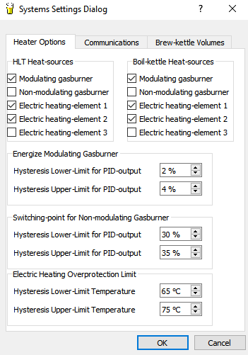
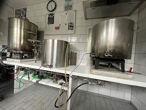
Bij Heater Options: this dialog screen is used to enter which burners are present in the brewing system. The picture above shows that both the HLT and the boil-kettle contain a modulating gasburner and two electric heating elements. The modulating gasburner is switched on if heating power is more than 4 % and is switched off again if heating power is less than 2 %. If a non-modulating gasburner would have been present, this one should be switched on and off at 35 % and 30 % heating power. And the electric heating elements are disabled when the temperature of the internal electronics reaches 75 % (and enabled again under 65 %).
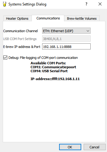
Bij Communications: this dialog screen is used to enter the COM-port number of the networkaddress of the brewing hardware and the settings for it. The information in bold in the middle of the screen shows what the PC program already has found. In this case, COM4 was found (the brewing hardware was also connected to the USB port) and the IP address of the brewing hardware is 192.168.1.11. The port number for the brewing hardware is always 8888. After entering the IP address and the port number here, all communication between the PC application and the brewing hardware uses the PC network.
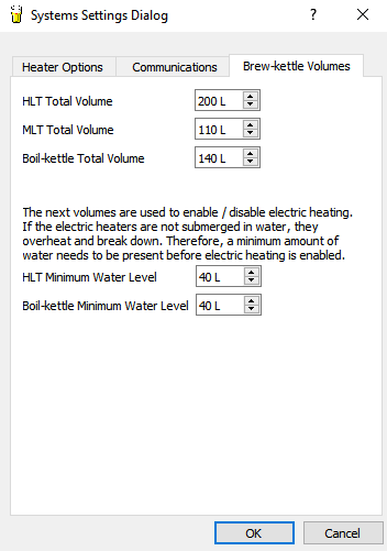
Bij Brew-Kettle Volumes: this dialog screen is used to set the minimum and maximum volumes of the brewing kettles. The minimum fluid level for the HLT and boil-kettle are relevant when electric heating is enabled. These values then contain the minimum fluid level with which the heating elements are still submerged. The large power of these heating elements would result in immediate breakdown if they are not submerged. So electric heating is disabled when the fluid level in the kettle is below this minimum level.
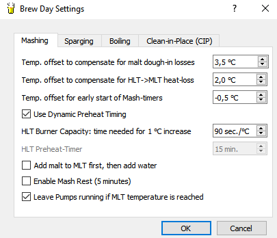
The first temperature offset is meant for initial mashing. It is the offset to add on top of the first mash temperature. It compensates for the decrease in temperature when malt is added to the water.
Suppose that the required first mashing temperature is equal to 63 °C. The HLT temperature setpoint is then set to 63 °C + this temperature offset.
The next temperature offset is meant for compensating the heat-losses between HLT and MLT. Even when the pipes are isolated well, there's always a (small) temperature loss. This offset compensates for the heat-loss.
The next temperature offset is meant for starting the mash-timer. In this case, the mash-timer is already started when the MLT temperature reaches 62.5 °C (and not at 63 °C).
With 'Dynamic Preheat Timing' a time is calculated based on the 'HLT Burner Capacity'. This time defines when the HLT burner should be enabled. Suppose that the next mash temperature step is 10 °C higher, with the current settings the burners would need 900 seconds (15 minutes) to reach that temperature increase. So the last 15 minutes of the current mash time interval are now use the preheat the HLT to the next temperature.
If this checkbox is unchecked, a fixed time ('HLT Preheat-Timer') is used.
During initial mashing, it is also possible to first add malt and then add (heated) water to it. If the checkbox is unchecked, all required water is added to the MLT first and then it is possible to add malt.
After initial mashing, it is possible to leave the pump off for 5 minutes (the 'Enable Mash Rest' option is checked). This prevents a stuck grainbed.
The last option here is to keep pumps running if the required MLT temperature is reached. Uncheck this option if you want to add malt directly when temperature is reached.
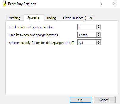
The system uses 'batch sparging', which means that sparging water is added in a couple of steps. The number of steps is defined here, typically this is set to 4 or 5 steps.
The time between two sparging steps can be entered as well here. This time is typically something between 10 and 20 minutes.
The system automatically calculates the amount of wort in liters to pump from the MLT to the boil-kettle during a sparging step. The first transfer of wort from MLT to boil-kettle can be made larger. Suppose that
every sparging step transfers 10 liter of wort to the boil-kettle. With the current setting, the first time transfer would result in 25 liters.
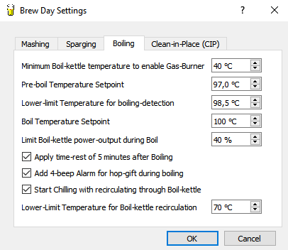
The first parameter prevents that the gasburner is enabled, while the boil-kettle is still empty. A minimum temperature inside the boil-kettle must be detected first, which is this parameter.
The second parameter contains the temperature setpoint value prior to boiling. During batch sparging, wort is collected inside the boil-kettle. The temperature of this wort should be set close to boiling, without the wort to actually boil.
The third parameter contains the detection limit for boiling. If the boil-kettle temperature exceeds this value, boiling is assumed and the brewing-system enters the boiling phase.
The next parameter contains the setpoint temperature for the boil-kettle during boiling. Set this value large enough, e.g. 105 °C, so that the PID-controller is set to maximum power (temperature during boiling never exceeds 100 °C).
The next parameter contains a power limit during boiling for the boil-kettle heaters. Set this percentage such that a nice rolling boil is obtained, not too wild but also not too slow.
After boiling is finished, a 5 minute timeout can be set (check the 'Apply time-rest of 5 minutes after Boiling' checkbox). This causes all hop and other particles to fall to the bottom of the boil-kettle. It prevents a stuck filter inside the boil-kettle, so it is generally recommended to enable this option.
A beep can be given when hop needs to be added to the boil. To enable this, check the option 'Add 4-beep Alarm for hop-gift during boiling'.
After boiling, it is possible to chill directly and pump the cooled wort into a fermentation bin. But it is also possible to cool the wort and have it returned to the boil-kettle. This will effectively cool the contents of the boil-kettle. This is
convenient when the counterflow chiller has insufficient capacity to cool directly to pitching temperature, for example in summer when it is hot. If you want to recirculate through the boil-kettle, enable the option 'Start Chilling with recirculating through Boil-kettle'. Recirculating through the boil-kettle is stopped when the boil-kettle temperature reaches a certain temperature.
This is the temperature defined in 'Lower-Limit Temperature for Boil-kettle recirculation'. After this, the wort is now cooled further and pumped into the fermentation bin.
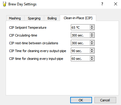
There is a separate state transition diagram made for cleaning of the brew system, this is called Clean-In-Place (CIP). This starts with filling the boil-kettle with a 1 % NaOH solution. This solution is first heated to the temperature as set in 'CIP Setpoint Temperature'.
If this temperature is reached, the NaOH solution is pumped through all pipes of the brewing system for a time as set by 'CIP Circulating-time'. After this time, the pump is switched off and the NaOH solution stays in the brewing system for a time defined by 'CIP rest-time between circulations'. After this, fresh water from the HLT is pumped for a certain time ('CIP Time for cleaning every output-pipe')
through every output pipe. Thorough rinsing is important, so this time should not be set too small. Next all inputs are rinsed (pump is off now) for a time set by 'CIP time for cleaning every input-pipe'.
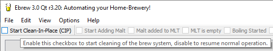
The option 'Clean-In-Place' can be activated on the menu-bar by checking the 'Start Clean-In-Place (CIP)' option.
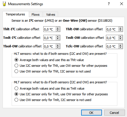
For every connected temperaturesensor, an offset (positive or negative) to the measured value can be added. This makes it possible to calibrate all sensors to the same reading.
Another setting is for the HLT temperaturesensors and how the HLT temperature is determined. Several options are possible: have two sensors (one I2C LM92 and one One-Wire DS18B20) read the HLT temperature and have these values averaged to obtain the HLT temperature. Another option is to only use the I2C sensor or the One-Wire sensor for the HLT temperature.
The same options can also be made for the MLT temperaturesensors.
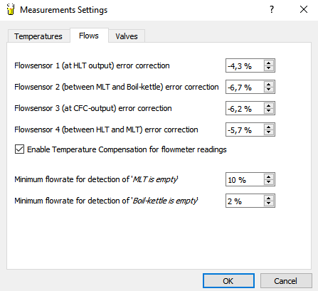
Every flowsensor can be calibrated individually to the number of liters flowing through it. Start with accurately measuring 20 liters and have that pumped through a flowsensor. The value of this flowsensor is then read by the PC application and can be corrected by the calibration value on this screen to the correct value.
Because the volume of a fluid increases when temperature increases, a temperature compensation can be enabled as well. This can be done by checking the option 'Enable Temperature Compensation for flowmeter readings'.
Last options here are two parameters that determine when the MLT or boil-kettle is pumped dry. During pumping from any of these kettles, there is a nominal flow rate (number of liters per minute). This is determined by the size of the pipes and the power of the pump and varies for every brewing system.
The nominal flow rate is measured by the PC program and when this flow rate is a set percentage of the nominal flow rate, the kettle is assumed to be empty. If you set these values too large, the brewing system stops too early with pump and fluid remains in the kettle. If you set these values too small, pump will remain running while nothin comes out anymore.
A value between 2 % and 5 % seems to give good results.
2. SOFTWARE ARCHITECTURE
The PC-program contains a number of important components which together make up the entire system. Because the C++ language is object oriënted, it is normal to identify a number of objects or classes. The main components for the PC-program are:
- A Scheduler with a number of tasks that need to be executed within fixed timing-intervals.
- State Transition Diagram (STD)"A state transition diagram is responsible for the overall control of the entire program.
- Various graphical objects (see the files hmi_objects.cpp and hmi_objects.h on Github), such as PowerButton, Tank, Pipe and Display. There's also a generic class called Actuator, of which the classes Valve and Pump are derived.
- Various control objects (see the files controlobjects.cpp and controlobjects.h on Github), such as PidCtrl (the PID-controller object), MA (moving-average filter object) and SlopeLimiter. The design and implementation of the PID-controller is described in more detail in Implementation of a PID Controller.
- Routines for the read- and write-operations from/to the COM-port and the Ethernet connection. The COM port is not physically present, but emulated through the USB-port. This is called a 'virtual COM port'.
The PC-program's main tasks are to allow the brewer to do all kinds of settings and adjustments needed for the brewing process (times, temperatures, parameters) and to send commands to the brewing-hardware on a periodic basis, using a standard communication protocol. The responses from the brewing-hardware are made visible to the various screens. The following screen-shot gives an overview of all project-files and screens used:
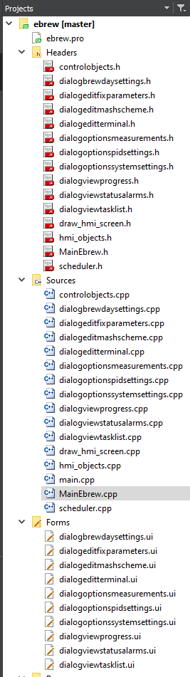
The total PC-application contains approximately 5600 lines of C++ code, of which the main-object (called MainEbrew) already contains 2200 Lines of Code (LOC).
Next to the PC-program there's a second important software system: the firmware for the ATmega328 on the Arduino Nano. This software-system also contains quite a lot of code: for revision R1.45 this was approximately 3550 lines of C-code. All-in-all: both systems together contain more than 9000 lines of C and C++ code!
Back to the Top of the Page2. SCHEDULER
The PC application demands strict timing-requirements. A lot of things need to be done at fixed time-intervals. Commands have to be send to the brewing-hardware, temperatures and volumes need to be read in, the screens need to be updated, etcetera. It would be nice to have a real-time embedded operating system (called an RTOS), but Windows is far from being real-time or embedded. To execute something every 100 milliseconds is already quite demanding. Fortunately, temperatures are not rapidly changing, so controlling this does not have to be very fast. But something is needed to make sure that all tasks are executed in time. For this I have written a separate scheduler component. A scheduler is a piece of software that makes sure that all tasks in a program are executed at the right time. The scheduler used here is non pre-emptive, which means that after a task has been started, it is not interrupted any more by another task. The next task can only start when this task has finished executing. This is sufficient for our brewing system. You just need to have a bit of attention for the duration of every tasks.
Tasks are easy to add with this scheduler component. To illustrate this, an excerpt of a bit of C code from the PC-application is given here:
	//-----------------------------------------
	// Now add all the tasks for the scheduler
	//-----------------------------------------
    scheduler->add_task("aliveLed"  ,   0,TS_LED_MSEC  ,Ebrew,SLOT(task_alive_led()));      // TASK 0
    scheduler->add_task("readTemps" , 100,TS_TEMPS_MSEC,Ebrew,SLOT(task_read_temps()));     // TASK 1
    scheduler->add_task("pidControl", 300,TS_PID_MSEC  ,Ebrew,SLOT(task_pid_control()));    // TASK 2
    scheduler->add_task("updateStd" , 400,TS_STD_MSEC  ,Ebrew,SLOT(task_update_std()));     // TASK 3
    scheduler->add_task("readFlows" , 600,TS_FLOWS_MSEC,Ebrew,SLOT(task_read_flows()));     // TASK 4
    scheduler->add_task("wrLogFile" ,1600,TS_WR_LOGFILE,Ebrew,SLOT(task_write_logfile()));  // TASK 5
Adding tasks is simple and convenient. The task task_update_std() for example executes the state transition diagram function every second (1000 msec.). You can also add an offset: task_update_std() is executed at time stamp 0.40 (400 msec.) and then at timestamps 1.40, 2.40, 3.40 etcetera. The PID controller, task_pid_ctrl(), is controlled in another way: the time-interval between two calls to this function is dependent of the parameter Ts, which is given in seconds. If this parameter is set in the PC-program to 20 seconds, this call here makes sure that the PID controller is executed every 20 seconds. As mentioned before, it is important to make sure that all of these tasks finish in time and do not take too much executing time, since this will delay other tasks. The scheduler is able to measure the time-duration and the maximum time-duration of every task. This information can be used for debugging purposes and looks like (result is from a log-file):
	Task-Name      T(ms) Stat T(ms) M(ms)

	-------------------------------------

	aliveLed        500  0x02   407  1339
    readTemps      2000  0x02 15236 15699
    pidControl     1000  0x02  1421  1767
    updateStd      1000  0x02   681  1040
    readFlows      2000  0x02 55684 55684
    wrLogFile      5000  0x02   167   167
From this, it appears that updateStd() had a maximum time-duration of 681 microseconds. Together with the code excerpt before, it gives a good insight in the behaviour of the various tasks. Debugging timing-issues is relatively easy to do. The scheduler itself is called from within an Timer object. This is done every 100 milliseconds. The main function of this function is to update all task-timers and to administrate if a task needs to be enabled of disabled. The execution of a task is not done here, only the administration!
Back to the Top of the Page3. STATE TRANSITION DIAGRAM (STD)
According to the free on-line dictionary of Computing, a state transition diagram (STD) is a "A diagram consisting of circles to represent states and directed line segments to represent transitions between the states. One or more actions (outputs) may be associated with each transition.". In terms of my brewing program, a STD is a central control function, that controls the various phases of the brewing process. A state can be a 'mash rest' phase or a 'mash preheat' phase. A transition from one state to another state can be made if a certain condition is TRUE (e.g. the 'temperature is OK'). Conditions in the STD below are given in RED. When a transition is made to another state, a particular action can be programmed (e.g. set pump on). Actions are given in GREEN. Summarized: there are states, transitions between states, conditions and actions. These need to be defined for the brewing program and is give here:
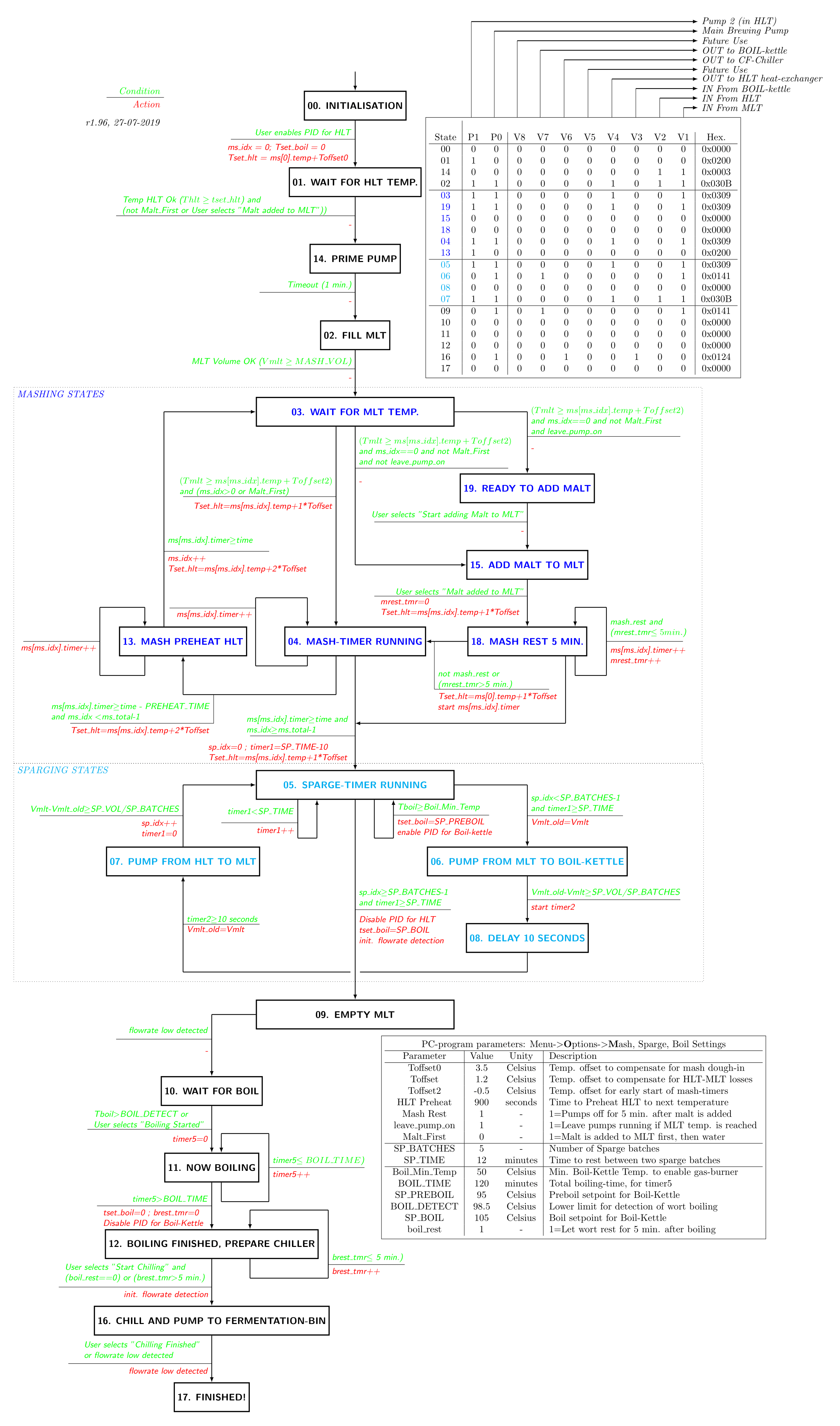
The total STD of the PC-program has become quite complex. A short explanation for every state is given here:
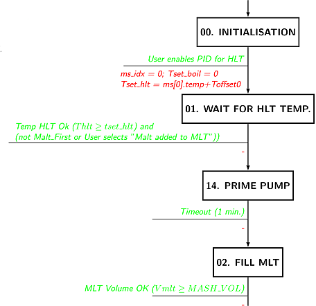
- 00. Initialization: this state is entered after the brewing program is started. It remains in this state until the brewer enables the PID controller. In this state, all valves are closed and the pump is off.
- 01. Wait for HLT temp.: the brewer has enabled the PID controller and water in the HLT is heated. The program remains in this state as long as the required temperature has not been reached. If the option "Add Malt First" is checked, you can add the malt to the MLT in this state.
- 14. Prime Pump: The magnetic pump is a non self-priming pump and needs to be filled with water in order to be able to operate. Filling the pump is done in this state: water runs from the HLT into the pump for 1 minute.
- 02. Fill MLT: The HLT temperature is OK and the pump is switched on. The MLT is now filled with the pre-set amount of water.
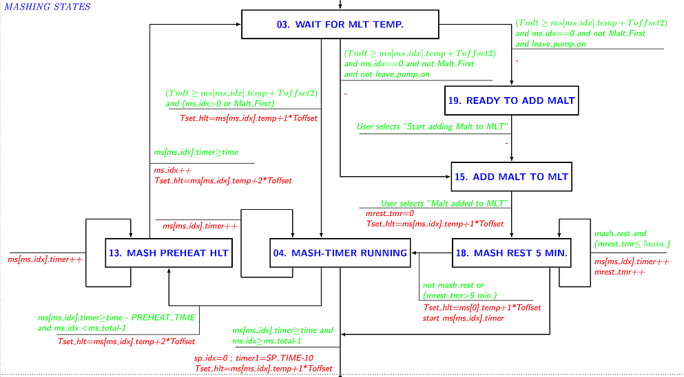
- 03. Wait for MLT Temp.: Remain in this state as long as the MLT temperature has not reached the required dough-in temperature.
- 19. Ready to add Malt: The MLT temperature has reached the required MLT mash-in temperature. In this state, water keeps on circulating through the MLT and the HLT heat-exchanger, because the pump is still enabled. If the option 'Start adding malt to MLT' is checked in the menu-bar, the next state is entered.
- 15. Add Malt to MLT: This is a manual action for the brewer: the milled grains are added to the water in the MLT, which has now reached the proper temperature. When adding the grains is finished, the brewer can indicate this to the PC-program. This state is executed only once and only when the option "Add Malt First" is unchecked.
- 18. Mash Rest 5 Min.: Give the milled grains a bit of time to soak water up. Starting the pump directly might clock up the filter bed.
- 04. Mash timer running: the mash rest timer is started, but has not reached a time-out yet. The program remains in this state as long as the timer is running. If all temperature-time pairs have been executed, a transition is made to the sparging phase (05. Sparge Timer Running). This state controls, together with the states 03. Wait for MLT Temp. and 13. Mash preheat HLT the entire temperature-time trajectory of the mashing process. These states are activated multiple times (dependent of the number of temperatures set) in sequential order.
- 13. Mash preheat HLT: the entire mash rest is not finished yet, but the HLT is already preheated to the next temperature (the pump is switched off now to prevent that the MLT is heated as well). When a time-out occurs from the mash rest timer, a transition is made to 03. Mash in progress and the mash-index is increased by 1.
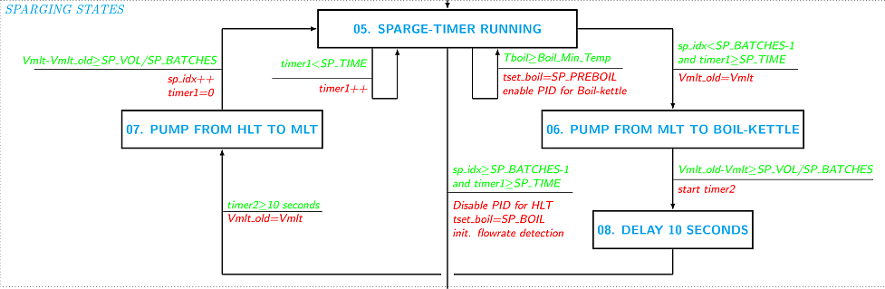
- 05. Sparge Timer Running: this state is activated when all temperature-time pairs have been handled. The mashing phase is now finished and sparging is started. Upon entering this state for the first time (coming from state 04. Mash timer running), a transition is made directly to state 06. Pump from MLT to Boil-Kettle. This pumps a part of the wort to the boil kettle. In all other cases this state remains active for a pre-set time (typically 15-20 minutes). If time-out occurs, new fresh water is added from the HLT. A transition to state 09. Empty MLT is made when the number of sparging sessions is equal to the pre-set number of sparging sessions (typically 4-5 times). This means that we are done with the sparging process.
- 06. Pump from MLT to Boil. A part of the wort is pumped from the MLT to the boil kettle. When the proper amount of litres has been transferred, a transition is made to state 07. Delay 10 Seconds.
- 07. Delay 10 seconds, this state remains active for only 10 seconds. Its purpose is to let the system rest a little.
- 08. Pump from HLT to MLT. In this state, fresh water of 80 °C from the HLT is pumped to the MLT. When the proper amount of litres has been transferred, a transition is made to state 05. Sparging Rest and the sparging index (sp_idx) is increased by 1. Cycling through the states 05 -> 06 -> 07 -> 08 is repeated a couple of times and this is made adjustable in the PC-program.
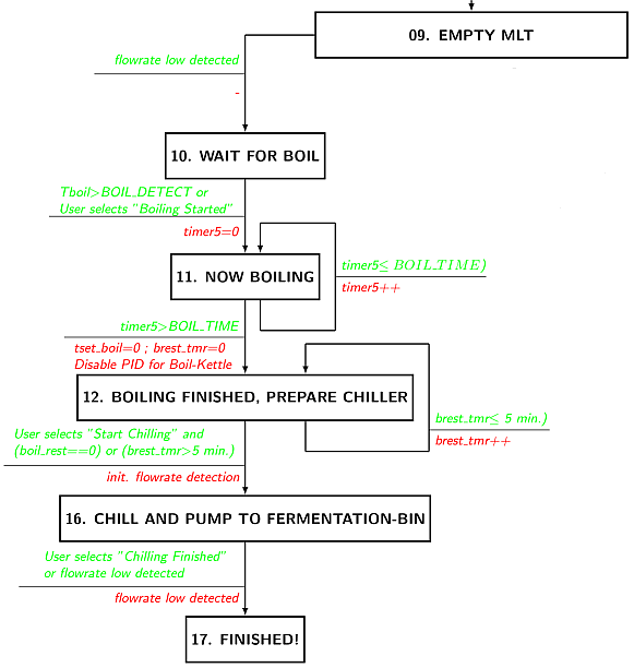
- 09. Empty MLT. If sparging is completed, this state is activated. All wort from the MLT is now pumped into the boil kettle.
- 10. Wait for Boil. All wort now sits inside the boil kettle, but it is not boiling yet. Only when it is actually boiling, a transition is made to the state 11. Now Boiling. Since there are no temperature sensors inside the boil kettle, the brewer needs to indicate manually to the PC-program that boiling has indeed started. After the brewer has done this, the transition to the state 11. Now Boiling is made.
- 11. Now Boiling. This state is activated when boiling has started, as indicated by the brewer. A boiling timer is started and as long as this timer has not timed-out, the PC-program remains in this state.
- 12. Boiling finished, prepare Chiller The boiling-timer has timed out and cooling the wort and pumping it into the fermentation bin can commence. When the counterflow chiller (CFC) is ready and cooling water is running through it, the brew can indicate this in the PC-program with another manual action. After this, a transition is made to the state 16. Chill & Pump to Fermentor.
- 16. Chill & Pump to Fermentor. The boiling-hot wort is pumped through the counterflow chiller and directly into the fermentation bin. After all wort has been transferred to this bin, the brewer can indicate this with a manual action in the PC-program. A transition is then made to state (17. Finished!).
- 17. Finished!. End of the brew day. This state is a dead-lock and does not contain any transitions to other states. If you want to start a new brewing session, you need to restart the entire PC-program.
The table (upper right corner) shows, for every state given, which valves are open (1) or closed (0) and whether or not the pump is on (1) or off (1). By designing such a table, the behaviour of the various valves becomes very defined. You always know exactly when a valve (or pump) is open or closed, given the state the STD is in. There are many more details to tell about this state transition diagram, but this will be sufficient (I hope) to give you an idea about the functionality. The STD is called once every second from the scheduler.
Back to the Top of the Page5. FIRMWARE FOR ARDUINO NANO / ATmega328
the firmware contains the C source-code for the ATmega328 microcontroller and has not much to do with the design of the PC-program described above. Both software systems do communicate with each other, using the Ethernet connection or the virtual COM port function of the USB connection. A big advantage of the use of a microcontroller is that all hardware related and often time-critical tasks no longer have to be handled by the PC-program. A microcontroller is much better suited for this. At the PC side, we use the Arduino hardware boards. Prior to use, the Arduino Software Environment needs to be installed. This already installs all the drivers needed for the virtual COM port and the USB connection. At the microcontroller side, the story is a bit different. Fortunately we do not have to dig into USB communication (complex!), but we can use existing routines for serial communication. The microcontroller used (ATmega328P) contains a component called USART, which stands for Universal Synchronous/Asynchronous Receiver/Transmitter). As long as you have the proper USART library, it is relatively easy to start with serial communication. Settings used here are 38400,N,8,1 which means: 38400 Baud, no parity bit, 8 data-bits and 1 stop-bit. This is of course identical to the settings in the PC-program.
Back to the overall design of the microcontroller software. I do not use Arduino sketches and the Arduino Programming Environment, since it is too limited for what I need. From some sketches I made proper C libraries, others I wrote myself. As usual for a C project, for every component a C source-file with a header-file (.h) is made. Together this contains all the necessary routines for such a component. For example: the I2C module (with files i2c.c and i2c.h) contain all functions for I2C communication, including specific routines for the ICs used here, such as the DS2482. The overall architectural design looks like the following:
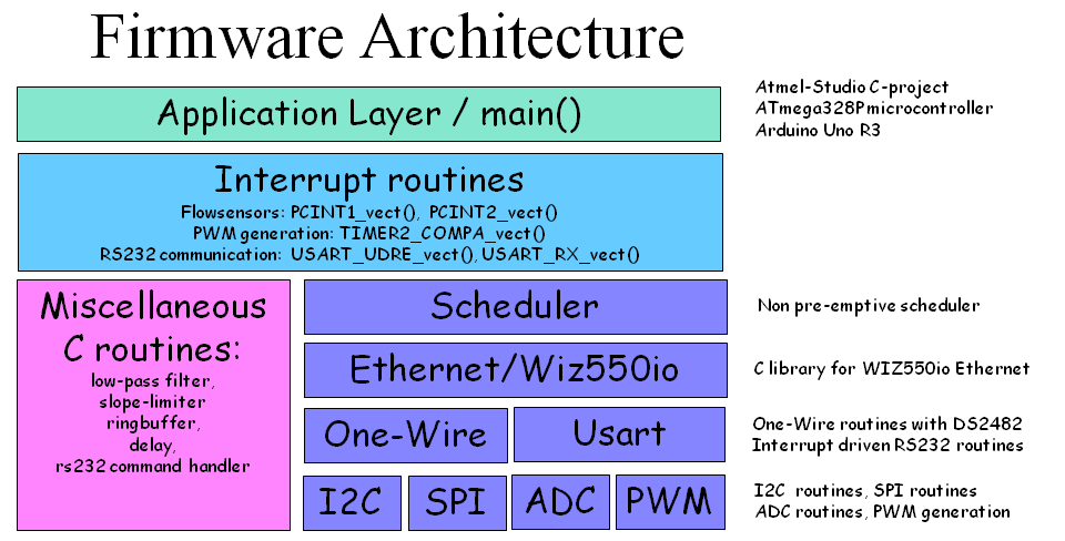
Low-level routines: As you can see in the picture, there are libraries for I2C, SPI, ADC, PWM, One-Wire and USART. Basically for every low-level hardware component of the microcontroller. In order to really understand these libraries, you need to read the ATmega328P microcontroller data sheet. Especially if you would like to make adjustments. But, since the ATmega328P is a very popular microcontroller, there are many good working examples available.
Interrupt routines: The interrupt routines are time-critical pieces of code that cannot wait until the scheduler has time for them. It needs to be executed as soon as something happens. For the embedded design engineer it is important to keep these routines as small as possible: you just cannot start to wait until something happens in such a routine. A nice example of the use of such an interrupt routine are the flow-sensors. These are connected to two port pins of the microcontroller. As soon as a pulse comes in from a flow-sensor, an interrupt is generated by the microcontroller. The interrupt source routine does nothing more than to increase a software counter. Every flow-sensor has it's own unique interrupt routine. Besides these routines there is also a timer interrupt defined for the scheduler. This one is executed every millisecond. Finally there are two more interrupts defined for the serial communication. If the USART hardware from the microcontroller has received a byte, an interrupt is generated. The interrupt routine merely stores the byte read into a ring-buffer. Something similar happens when there is data in the ring-buffer that needs to be send to the PC-program.
Next to these low-level libraries, there is also a miscellaneous library. This library contain functions that deal with signal processing, such as filtering. It contains a moving-average filter (which is a low pass filter) and a slope-limiter function. Furthermore a ring-buffer for the serial communication and a RS232 command handler. Every command from the serial interface is processed by this function.
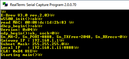
Ethernet/Wiz550io: the brewing-hardware is equipped with a WIZ550io Ethernet module, which is controlled through the SPI interface. The C-libraries are derived from several Arduino sketches (which were a mess to read). With this addition it becomes possible for the brewing hardware to send/receive commands using the UDP protocol, instead of using the USB connection. During powerup, the brewing hardware sends status info to the USB port, such as the local IP address of the brewing hardware. It looks like this:
The scheduler from the PC-program is reused here as well. So the software is used on various platforms.
Back to the Top of the Page